** Must be connected to Ground when the Analog Input is set to Single-Ended Mode.
It is recommended to use a separate ground cable for each single-ended analog signal/cable and twist or tie
them together.
*** This is a 5 V supply that can provide up to 100 mA for external use.
The supply is protected against short to ground and keeps the current below 400mA in a continuous short.
**** This is a 10 V supply that can provide up to 25 mA for external use.
The supply is protected against short to ground and keeps the current below 100mA in a continuous short.
1.3.2.1.3.4.1 Analog input specification
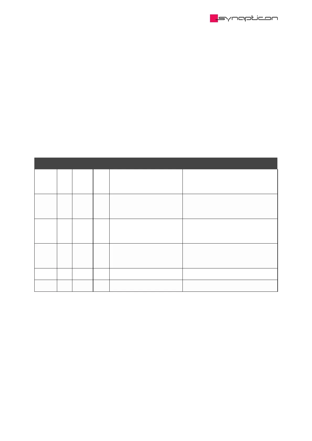
1.3.2.1.3.4.1.1 Differential
Symbol Min. typical Max. Description Impact
V -10V +10V The input voltage between the
positive and negative input
pins.
Any voltage out of this range causes
saturation to min/max ADC value
V -10V 0V +10V The common mode voltage. Any voltage out of this range causes
saturation and inaccuracy in the
measurements.
V -15V +15V The tolerable voltage between
the positive input pin and
GND.
Any voltage out of this range damages
the analog input’s circuitry.
V -15V +15V The tolerable voltage between
the negative input pin and
GND.
Any voltage out of this range damages
the analog input’s circuitry.
R 27.2kΩ Internal input resistance
Error -1% +1% Error in ticks
diff
cm
in,P
in,N
i