Allowed discrepancy between digital inputs 100 ms
See safety diagnostic section
Safe brake output (SBC)
Number of digital outputs 2 (dual-channel safety output for one brake
system)
Max. output voltage Servo drive main power supply (48 VDC)
Min. output voltage 0 V
Max. current. 1 A
Max. peak current. 4 A
Note
This PWM controlled brake is configured by the same object as the regular brake.
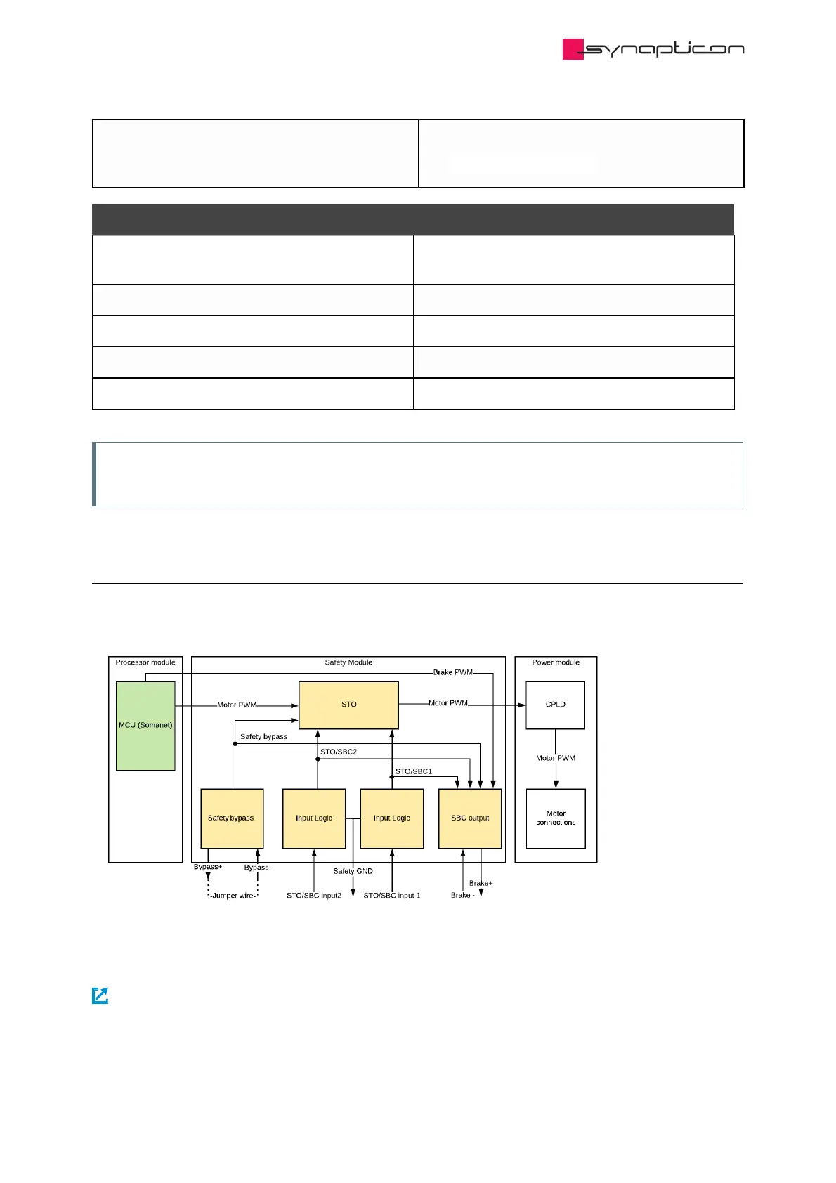
1.3.4.2.3 Block diagram
Simplified block diagram of SOMANET Node Safety:
For details of the connectors please refer to:
Safety connectors