III-60
System Operation
The following AC components are discussed in detail in this section:
1. Compressor/Clutch Assembly
2. Condenser
3. Receiver-Drier
4. Expansion Valve
5. Evaporator Coil
1. Compressor/Clutch Assembly
The compressor/clutch assembly is the heart of the system. When the clutch is engaged,
the compressor pumps refrigerant and oil around the system. It raises the temperature
and pressure of the refrigerant gas, and forces it to the condenser where it changes
state and becomes a liquid. The compressor also sucks the vaporized refrigerant out
of the evaporator and back inside itself in the form of gas. One way valves inside the
compressor separate the compressed gas (high pressure) side of the system from the
suction (low pressure) side. Figure 2-3 shows a cutaway view of a compressor with the
high and low pressure sides noted.
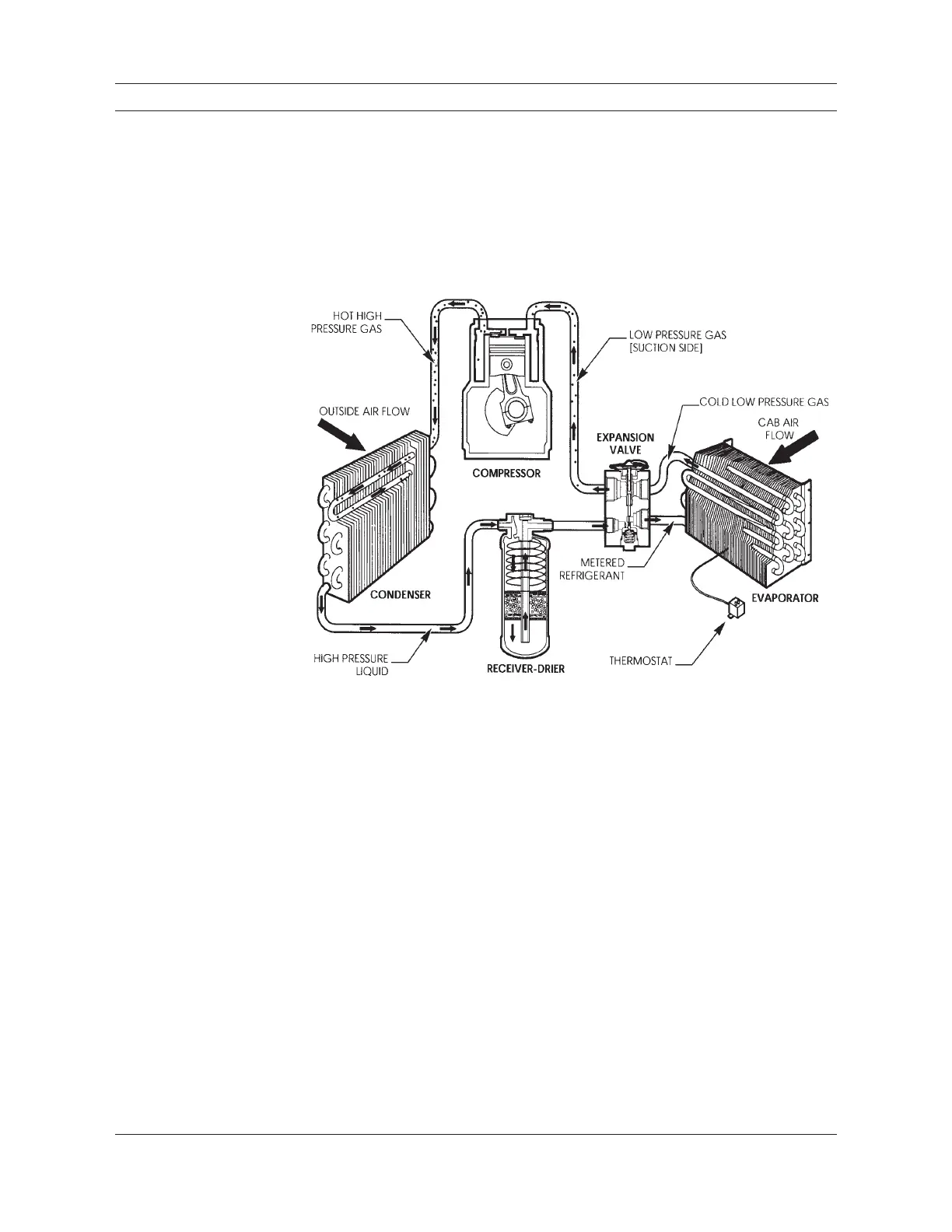
Figure 2-2
Air Conditioner components
are connected together to
illustrate system operation.
The components shown are
not to scale. The refrigerant
and refrigerant oil are clear
in color and not visible in
this drawing. The small ar-
rows inside the components
and connecting hoses show
the direction of refrigerant
flow (refrigerant circuit).

 Loading...


