IV-65
HYDRAULIC UNITS
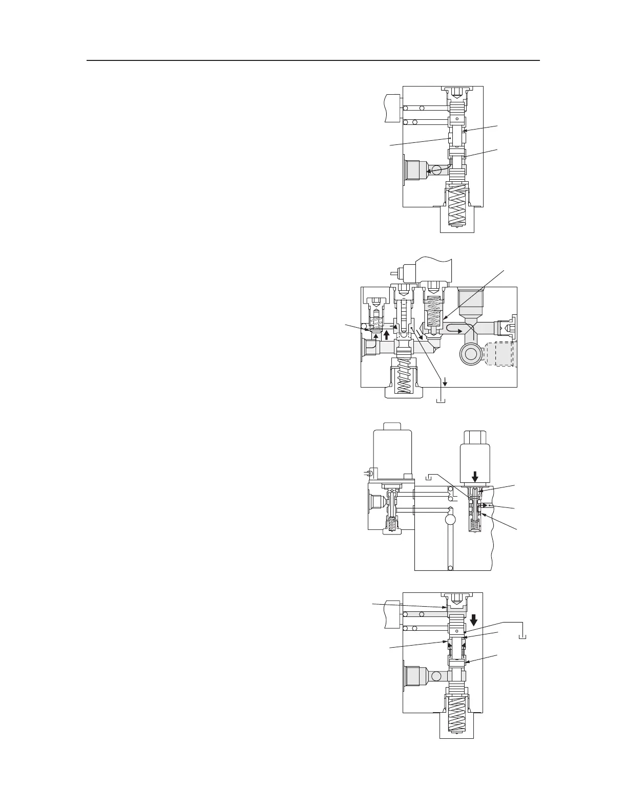
CONTROL VALVE (SUB)
T7D901
4
P
5
3
T7D902
6
3
P
7
2
T7D903
8
10
9
T7D904
4
P
5
C
3
OPERATION
When the solenoid A is not electrified
The port P and the circuit of the port 3 are connected
through the spool (4).
The hydraulic oil from the port P flows into the port
3, while the port P and the circuit (5) of the port 1
are shut off.
The port P and the circuit of the port 2 are shut off
by the poppet (6).
The hydraulic oil from the port 2 pushes up the
plunger (7), flows into the circuit of the port 1, and
enters together with the oil from the port 1 into port
T.
When the solenoid A is electrified
A magnetic field is generated around the coil that
causes the push rod to be pulled downward, pushing
the spool (8) downward. Then the hydraulic oil from
the port P flows through the passages (9) and (10)
and enters the chamber C.
The hydraulic oil entering into the chamber C moves
the spool (4) downward to shut off the ports P and 3.
This connects the port P and the passage (5), allow-
ing the oil flow from the port P to port 1.

 Loading...


