IV-62
HYDRAULIC UNITS
CONTROL VALVE (HIGH FLOW)
Adjusting the Relief Valve Pressure
• Engine : Rated R.P.M.
• Hydraulic Oil Temp. : 50~60°C
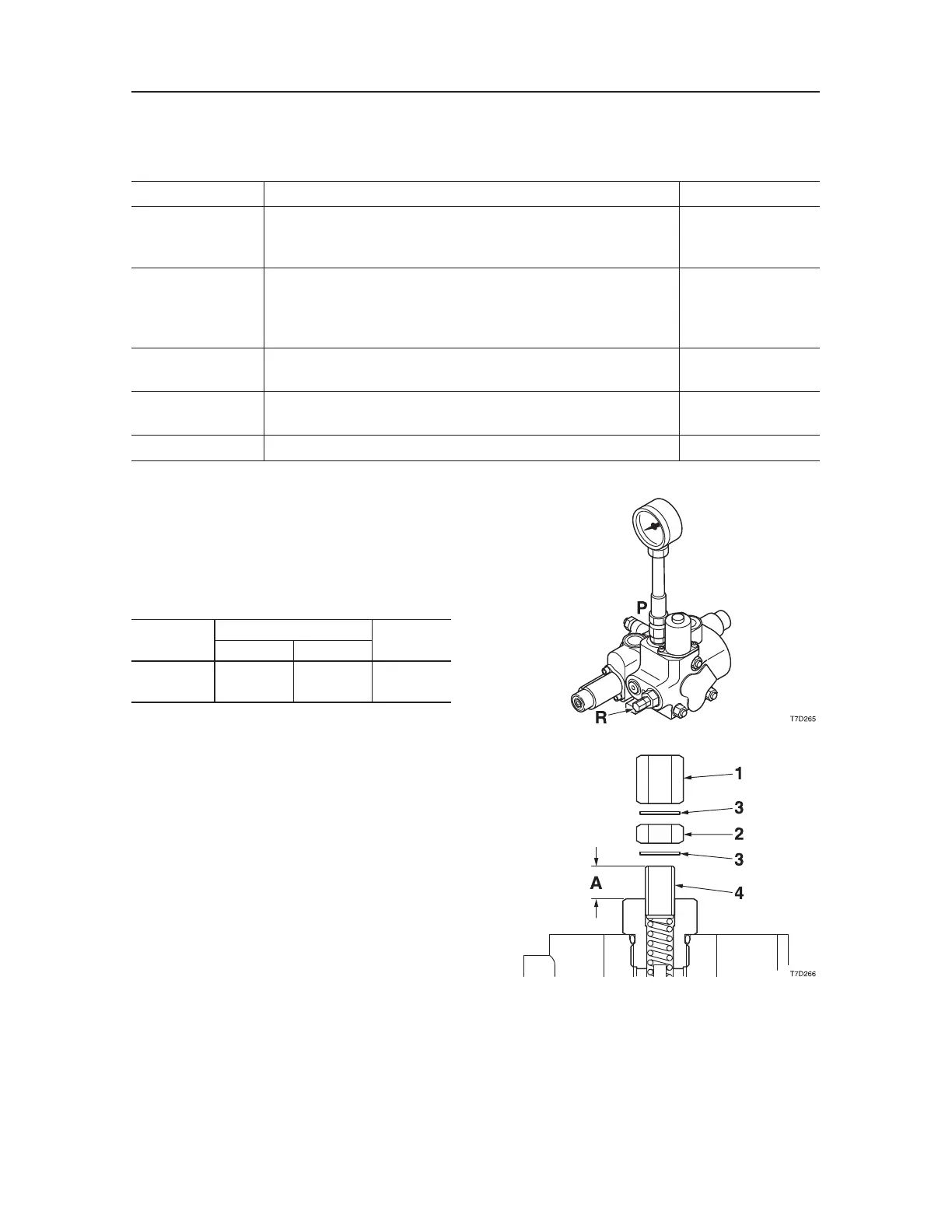
• Mount the pressure gauge on the pressure detec
-
tion port, operate the desired hydraulic circuit and
measure the relief pressure.
Circuit
Pressure Detection Port
Relief
Valve
Port Position
Size
Auxiliary
(High Flow)
P G 1/2 R
1. Remove the cap screw (1), shim (3), lock nut (2)
and shim (3) in this order.
• The shims must be replaced for every adjust
-
ment.
2. Make sure to record the dimension of the section
A of the setscrew (4).
3. Adjust the set value by turning the setscrew (4).
Turning clockwise .................
raises the set pres-
sure.
Turning counterclockwise .....
lowers the set
pressure.
• Change of pressure per turn: 9 MPa
4. In order to keep the setting screw from turning
after pressure has been adjusted, tighten the
locknut while at the same time holding the set-
ting screw firmly in place.
5. Operate the relief valve once more to confirm
that the pressure that has been set it stabilized.
INSPECTION AND ADJUSTMENT
Checking the Parts
Parts Judgment Criteria Treatment
Solenoid coil • When the solenoid is burned, short-circuited, or has a wire
break
• Wiring short-circuit or wire break
• Replace
• Replace
Body • Scratches, rust, or corrosion at the sliding parts with the spool
• Scratches, rust, or corrosion of the seal part in contact with the
O-ring
• Other damage considered to impair the normal functions
• Replace
• Replace
• Replace
Spool, plunger • Damage on the outer circumference which catches a fingernail
• No smooth movement
• Replace
• Adjust or replace
Spring • Rust, corrosion, deformation, breakage, or other notable dam-
age
• Replace
O-Ring
±±
• Replace

 Loading...


