III-7
MACHINE CONFIGURATIONDRIVE SYSTEM
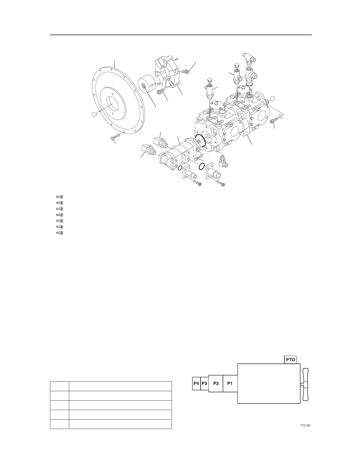
1. Engine Housing
2. Coupling
3. HST Pump
4. Gear Pump
Pump Coupling
A: Apply molybdenum disulfide grease.
B:
210~230 N·m
C:
55 N·m
D:
116 N·m
E:
47.1 N·m; Apply thread-locking compound
F:
132 N·m
G:
69 N·m
The pump coupling connects the engine flywheel and
the hydraulic pump·s drive shaft. It is constructed so
that it absorbs vibrations, torsions, impact and out of
center of the engine and hydraulic pump.
• Refer to the table concerning the responsibility of
each of the pumps shown in the drawing at right.
P1 Left Travel
P2 Right Travel
P3 Lift Arm, Bucket, Auxiliary
P4 Charge Pressure, Pilot Pressure
PTO High Flow
T7C102
X
X
1
C
G
G
4
E
3
D
F
F
B
B
2
A

 Loading...


