IV-48
HYDRAULIC UNITSCONTROL VALVE
Load Check Valve
This valve prevents oil from flowing backward due
to the load pressure C from the actuator port (6) dur-
ing switching of the spool.
Main Relief Valve
A main relief valve is mounted between the pump
circuit and tank circuit of each inlet housing and
serves to maintain the circuit pressure at the set
value.
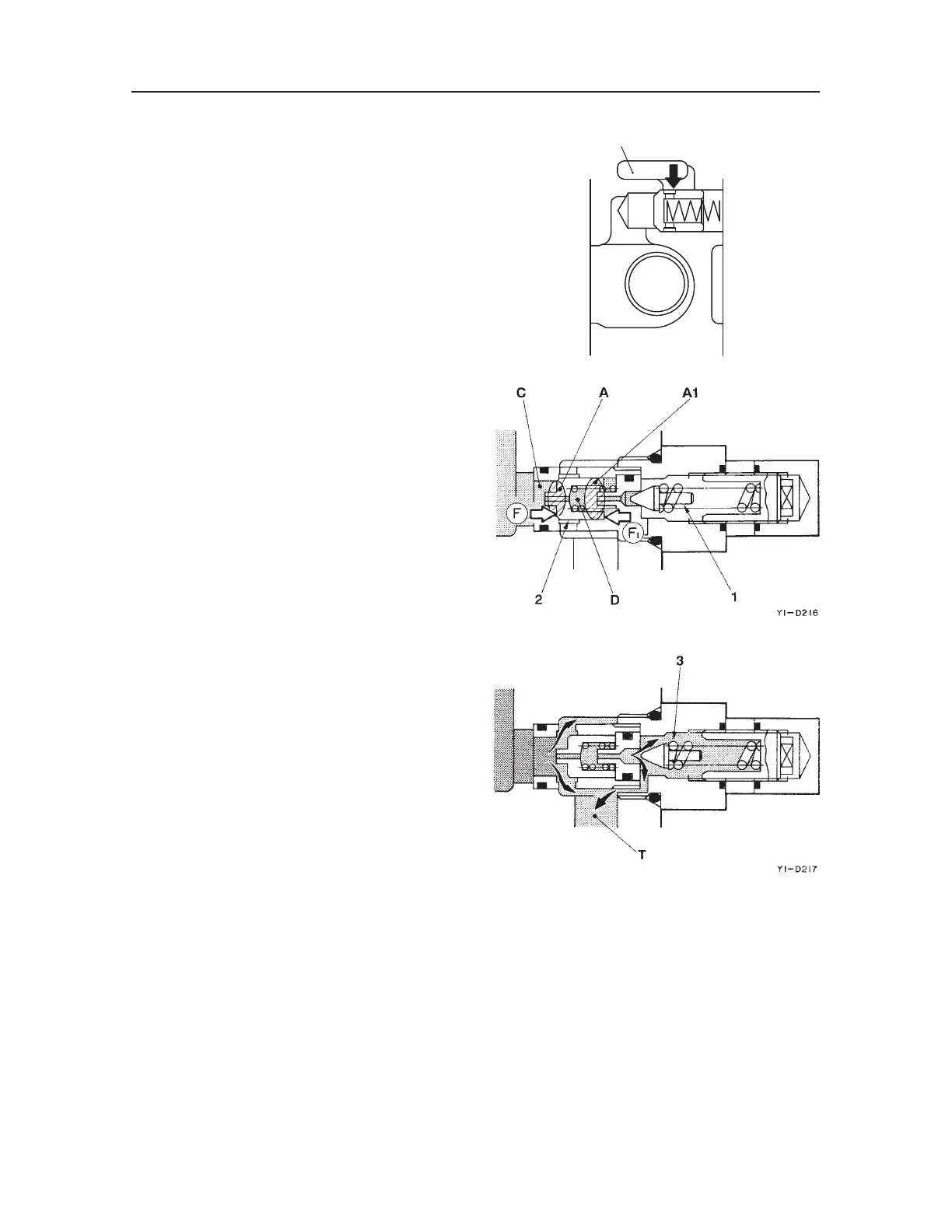
When the Relief Valve is NOT Operating
When the pressure in the circuit is low with respect
to the set value, the relief valve maintains equilib-
rium. Hydraulic oil from the pump passes through
the orifice from chamber C and arrives at the spring
chamber D and the needle valve (1). On the other
hand, forces F and F1 are acting in the respective ar-
row directions on both sides of the main poppet (2).
F = P × A Fl = P × A1
P: Pressure A, A1: Cross Sectional Area
Since the cross sectional area of A is less than that of
A1, the main poppet (2) is pushed by the force
“F1-F” to the seat surface on the left side.
When the Relief Valve is Operating
If the circuit·s pressure becomes greater than the set
value of the spring (3), the needle valve (1) is pushed
to the right by hydraulic pressure and oil flows to the
tank passage T. When this happens, a pressure dif-
ferential is generated between the two ends of orifice
of the main poppet (2), and this hydraulic pressure
pushes the main poppet toward the right. As a result,
the pressurized oil in the circuit flows to the tank
passage.
This operation maintains the pressure in the circuit
at the set value.
T9D204
C
6

 Loading...


