III-19
MACHINE CONFIGURATION
TRAVEL SYSTEM
DISASSEMBLY AND ASSEMBLY
Removing the Steel Track
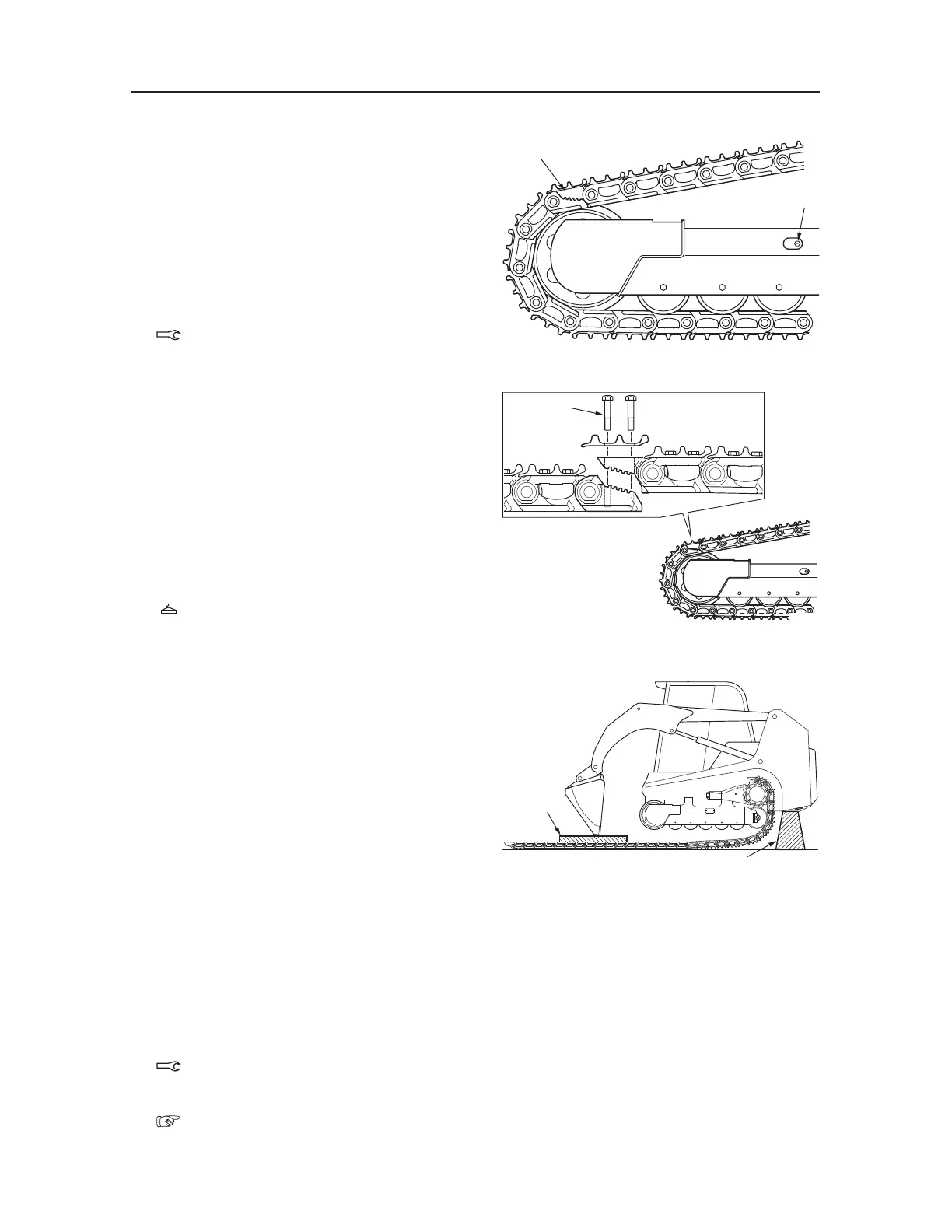
Stop the machine so that the master links are
positioned at the top of the idler.
1. Loosen the track tension.
When loosening the grease discharge valve (1),
turn it slowly. Do not loosen it beyond the point
where grease starts to ooze out. If it is difficult
for the grease to come out, move the machine
forward and in reverse.
Grease discharge valve: 59 N·m
2. Remove the master bolts (2) and disconnect the
master links (3).
3. Place the wooden blocks (4) with a height of 20
cm under the cutting edge of the bucket and tilt
the bucket forward and lower the lift arms to
raise the machine front.
4. Suspend the machine rear and place a block (5)
under the machine rear.
5. Rotate the travel motor slowly in the reverse
direction to remove the track
Track: 401 kg
Installing the Steel Track
1. Place the wooden blocks (3) with a height of 20
cm under the cutting edge of the bucket and tilt
the bucket forward and lower the lift arms to
raise the machine front.
2. Suspend the machine rear and place a block (4)
under the machine rear.
3. Position the track beneath the frame.
• Be careful not to mistake the installation di-
rection of the track.
4. Engage the links in the sprocket, then rotate the
travel motor slowly in the forward direction to
wrap the track around the frame.
5. When the master link reachs a point just to the
top of the idler, stop rotating the sprocket and
lower the machine to the ground.
6. Connect the master links and install the shoe
plate and the master bolts.
Master bolt: 225±10 N·m
7. Adjust the track tension.
“II. Specifications, Standards for Judging
Performance”

 Loading...


