III-12
MACHINE CONFIGURATIONDRIVE SYSTEM
Removing the Hydraulic Pump
1. Drain out the oil from the hydraulic tank.
“Removing the Hydraulic Tank”
2. Disconnect the drain hoses (1) and HST hoses
(2).
3. Disconnect the pressure switch connectors (3).
4. Disconnect the pilot hoses (4).
5. Disconnect the charge hose (5).
6. Disconnect the discharge hoses (6) and suction
hoses (7) from the gear pumps.
7. Remove the cap screws (8) and take out the hy-
draulic pump.
Cap Screw: 116 N·m
Apply molybdenum disulfide grease to the
spline section.
Installing the Hydraulic Pump
Follow the same procedure as for removal in the
reverse order.
Purging Air from the HST Pump
WARNING
When refitting the HST pump after repair or re-
placement, be sure to purge air before starting
the operation. Failure to do so can cause injury
or death due to unexpected machine move-
ment.
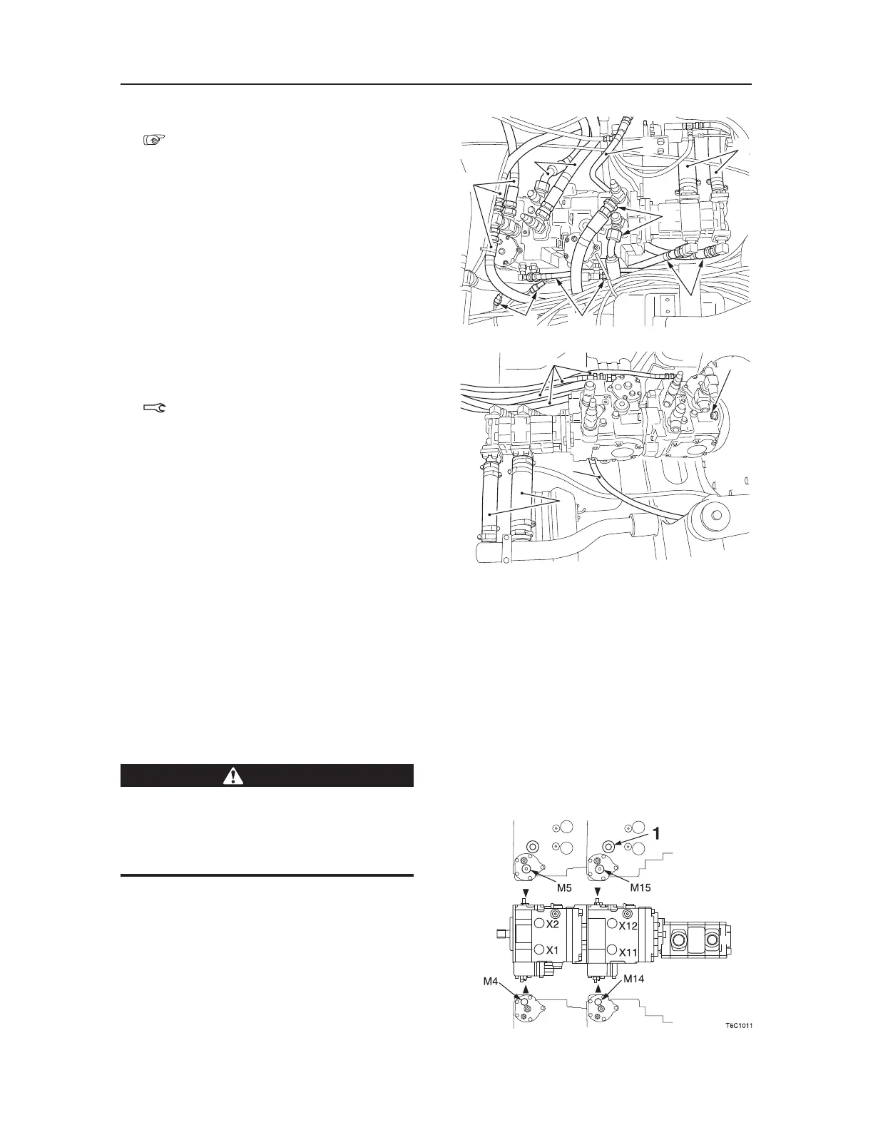
1. Before installing the HST pump on the machine,
fill the servo control chambers with hydraulic
oil.
a. Plug the pilot ports (X1), (X2), (X11) and
(X12) temporarily.
b. Supply hydraulic oil through the servo pres
-
sure gauge ports (M4), (M5), (M14) and
(M15) to fill the servo control chambers.
T7C111
7
2
6
4
3
1
2
5
T7C112
8
4
7
5

 Loading...


