III-65
Heater System Operation
Heater and air conditioner systems both have the same basic function of moving heat.
They take advantage of nature·s laws where heat energy always moves from a warmer
to a cooler area. In a heater system there is no “change of state” involved in system
operation. The system is sealed and operates under pressure, but the pressure is low
when compared to an air conditioner.
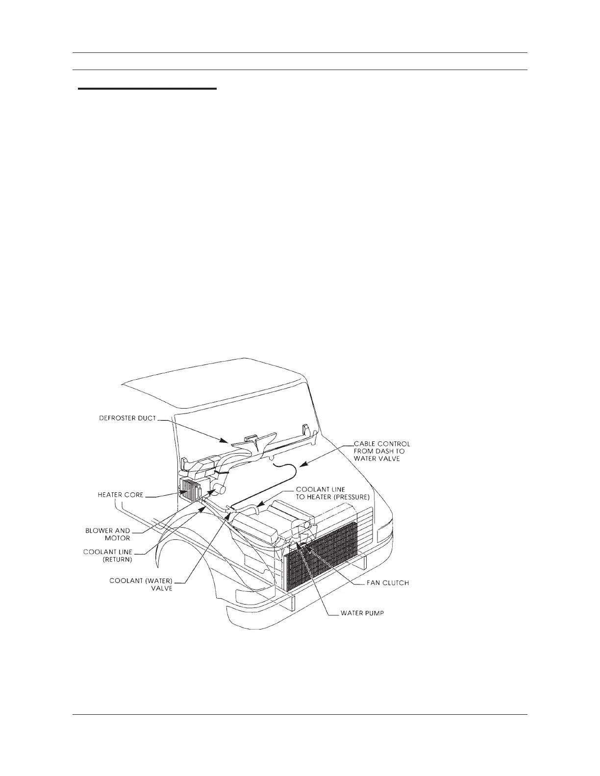
A heater system uses the engine coolant to carry excess heat energy to the cab air.
The heart of the system is the water pump. The water pump forces hot coolant through
a hose from the engine block and through the heater core. The coolant is returned to the
engine cooling system either at the suction side of the water pump or to the radiator.
A control cable, attached to a water valve between the water pump and the heater
inlet, is used to control the flow of coolant to the heater. The heater fan or blower forces
cab air through the heater core where heat energy moves from the engine coolant to
the air in the cab. Figure 2-9 illustrates the main heater system components. In-cab
controls, component housing and air vents are not shown.
The following heater components are discussed in detail in this section:
1. Heater Core
2. Water Valves
3. Defrosters and Ducts
4. Blowers and Fans
Additional heater controls, ducts, air vents, blend-air doors, temperature regulating
devices and auxiliary heaters may be installed as part of a heater system. These may be
air, vacuum, electrical or mechanically operated.
System Operation
Figure 2-9
This view of a heater system
shows the main components
and how they are connected.

 Loading...


