IV-33
HYDRAULIC UNITSGEAR PUMP
GEAR PUMP
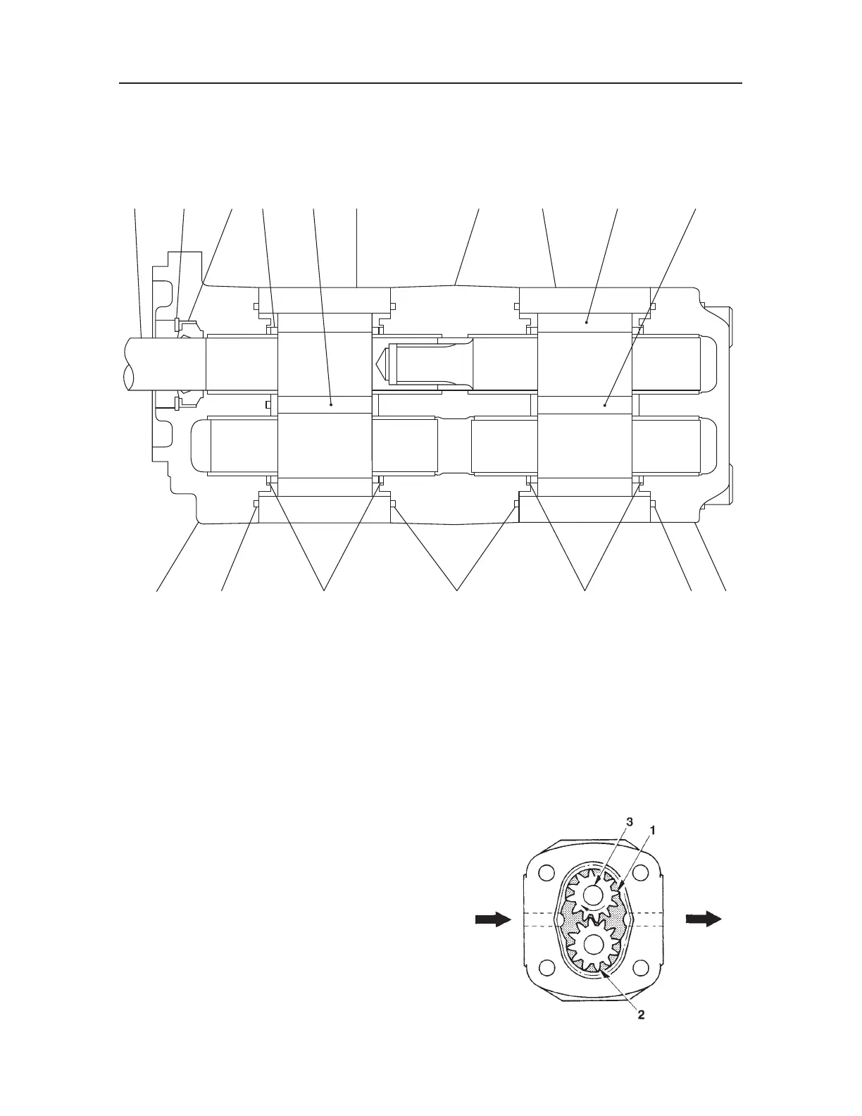
CONSTRUCTION
1. Flange
2. Rear Cover
3. Housing
4. Drive Gear
Gear Pump
The gear pump consists of a single gear case, inside
of which is a drive gear (1) and a driven gear (2)
engaged with each other. By turning the drive shaft
(3), the space between the case and the gears is filled
with oil. This oil is thus sent through the pump from
the inlet to the outlet.
5. Driven Gear
6. Bushing
7. Adapter Plate
8. Housing
9. Drive Gear
10. Driven Gear
11. Gasket
12. Gasket
INLET OUTLET
Y1-D101E
13. Oil Seal
14. Snap Ring

 Loading...


