IV-17
HYDRAULIC UNITSHST PUMP
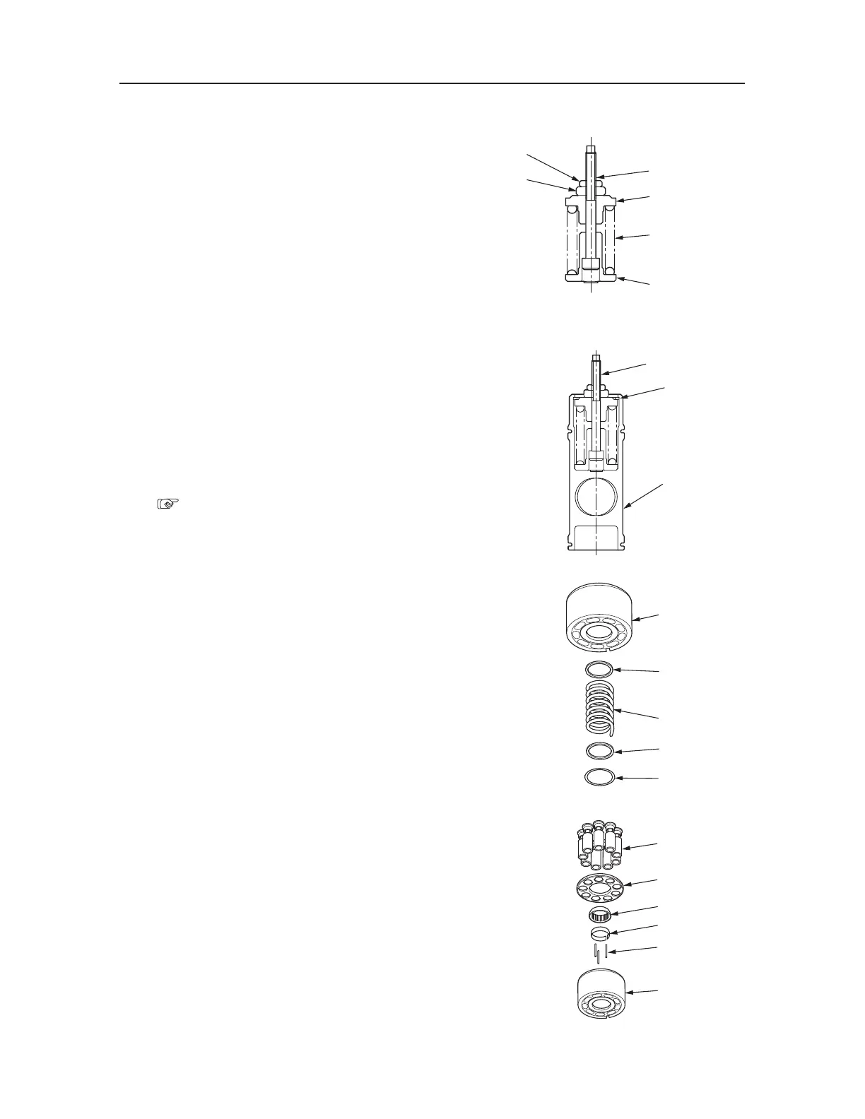
Assembly
Pump
1. Assemble the servo piston.
a. Install the spring guide (53), the spring (52)
and the spring guide (51) to the tie bolt (16).
b. Attach the nut (50), and tighten it manually
until it contacts the spring guide (51).
c. Attach the nut (49), and tighten it until it con
-
tacts the nut (50).
d. Install the spring assembly to the servo piston
(20), and attach the snap ring (48).
• Compress the spring by the press.
• Use a new snap ring.
e. Confirm that the spring load is applied to the
snap ring (48) and the tie bolt (16) rotates
freely.
f. Adjust the rotational torque of the servo pis
-
ton.
“IV-24”
2. Assemble the cylinder block.
• Lubricate individual components of the cyl
-
inder block with hydraulic oil in advance.
a. Install the washer (37), the spring (38), and
the washer (39) to the cylinder block (36).
b. Install the retaining ring (40) by compressing
the spring.
3. Assemble the cylinder block assembly.
a. Install the retainer ring (34) to the cylinder
block (36).
• Install the ring at the position 3.2 mm be
-
low the uppermost surface of the cylinder
block.
b. Install the three hold-down pins (35) to the
cylinder block (36).
c. Install the ball guide (33) to the cylinder block
(36).
S3F321
16
51
52
53
49
50
S3F322
20
48
16

 Loading...


