IV-7
HYDRAULIC UNITSHST PUMP
OPERATION
The pump covered here is a tandem pump for hy-
drostatic transmission. When combined together
with an HST travel motor, the speed of the motor
may be controlled from a speed of 0 to the specified
maximum, in smooth gradations and without the
switching of gears.
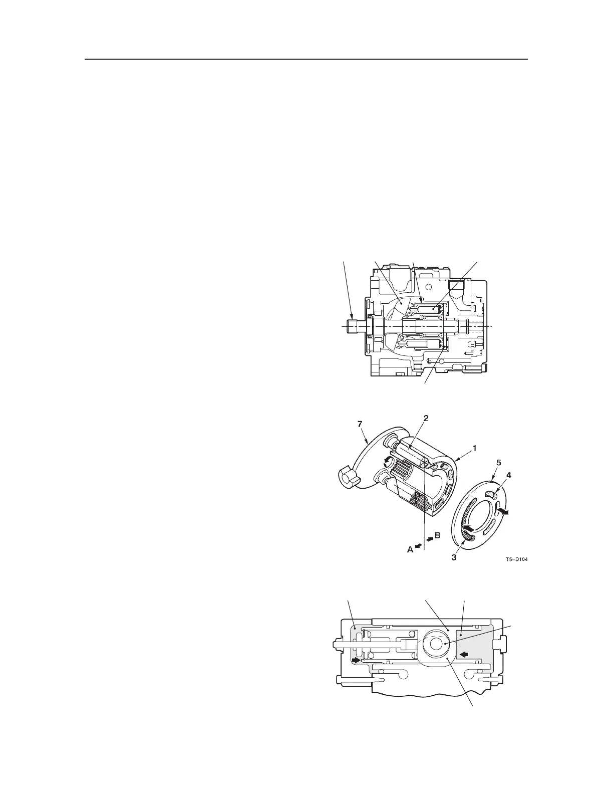
Hydraulic Pump
Cylinder block (1) has been constructed with nine
pistons (2) built in, and the end surface comes in
contact with the valve plate (5) containing intake
port (3) and exhaust port (4). Cylinder block (1)
rotates freely and is connected to drive shaft (6) via
the spline. Swash plate (7), on the other hand, is
connected to the housing and tilted somewhat, and
piston (2) is constructed to follow swash plate (7) in
its rotation.
Rotating drive shaft (6) at this point causes cylinder
block (1) to rotate, causes piston (2) connection to
cylinder block (1) to follow along with swash plate
(7) to move in a back-and-forth motion, and causes
the intake and exhaust pumps to begin working.
Thus the nine pistons (2) perform approximately a
single intake (A) or exhaust (B) sweep for each rota-
tion of cylinder (1), and operating drive shaft (6) in
continuous rotations allows you to perform a con-
tinuous stream of intake and exhaust operations.
Note that since the sweep capacity of piston (2) de-
pends on the degree of tilt of swash plate (7), the
tilt of the plate may be changed to modify the total
quantity of exhaust.
Displacement Control
Bearings are attached to both sides of swash plate
(1), the swash plate is connected to the housing so
that the degree of tilt may be changed, and piston (2)
is used to link the swach plate with control cylinder
(3).
In a neutral position, since the charge pressure of
swash plate (1) enters into chambers (4) and (5) to
preserve equal pressure, control cylinder (3) remains
at rest in a neutral position.

 Loading...


