III-36
MACHINE CONFIGURATION
CONTROL SYSTEM
T7C502
1
2
3
4
T7C503
5
8
6
7
9
DISASSEMBLY AND ASSEMBLY
Removing the lever Stands
1. Tilt up the canopy.
“Tilting Up the Canopy”
2. Remove the floor.
“Removing the Floor Frame”
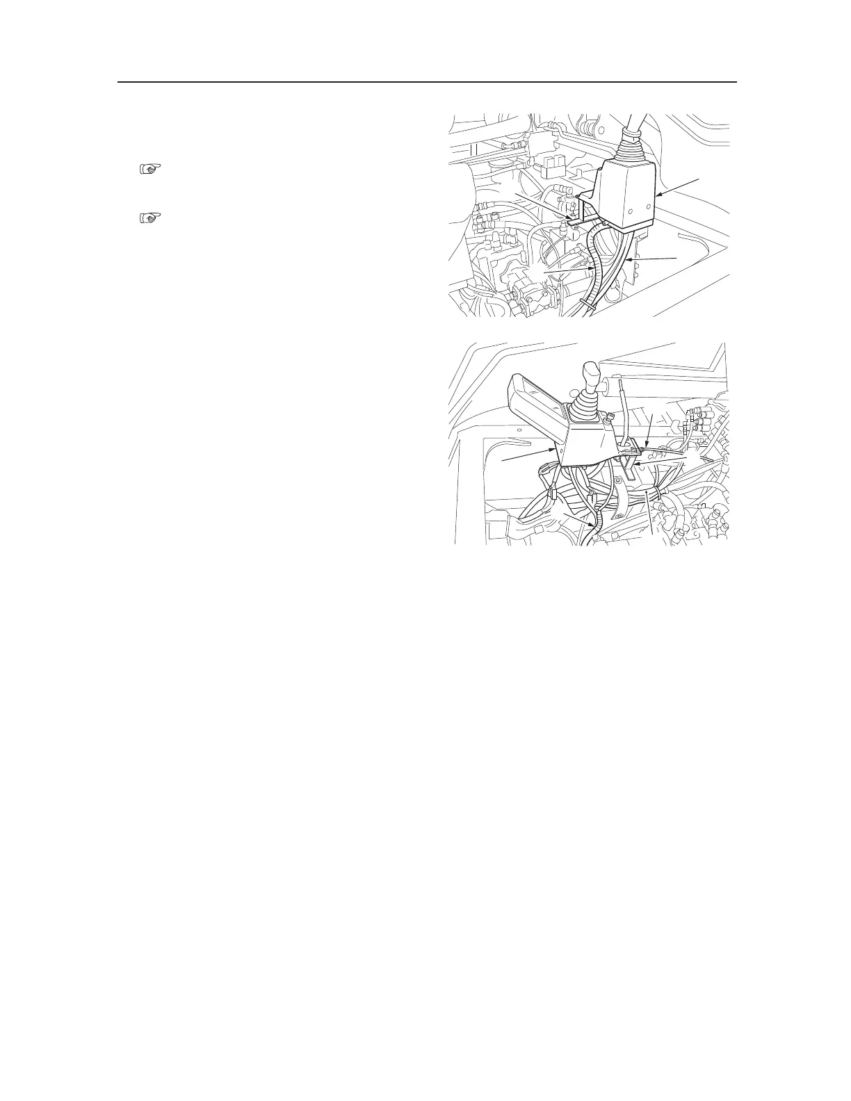
3. Remove the lever stand L.
a. Remove the cover (1).
b. Disconnect the hydraulic hoses (2) from the
pilot valve.
• Attach identification labels to individual
hoses for correct reassembling.
c. Disconnect the electric wiring (3).
e. Remove the bolts and bracket L (4).
4. Remove the lever stand R.
a. Remove the cover (5).
b. Disconnect the electric wiring (6).
c. Disconnect the hydraulic hoses (7) from the
pilot valve.
• Attach identification labels to individual
hoses for correct reassembling.
d. Disconnect the accelerator wire (8).
e. Remove the bolts and bracket R (9).
Installing the Lever Stands
Follow the same procedure as for removal in the
reverse order.

 Loading...


