II-21
SPECIFICATIONS
STANDARDS FOR JUDGING PERFORMANCE
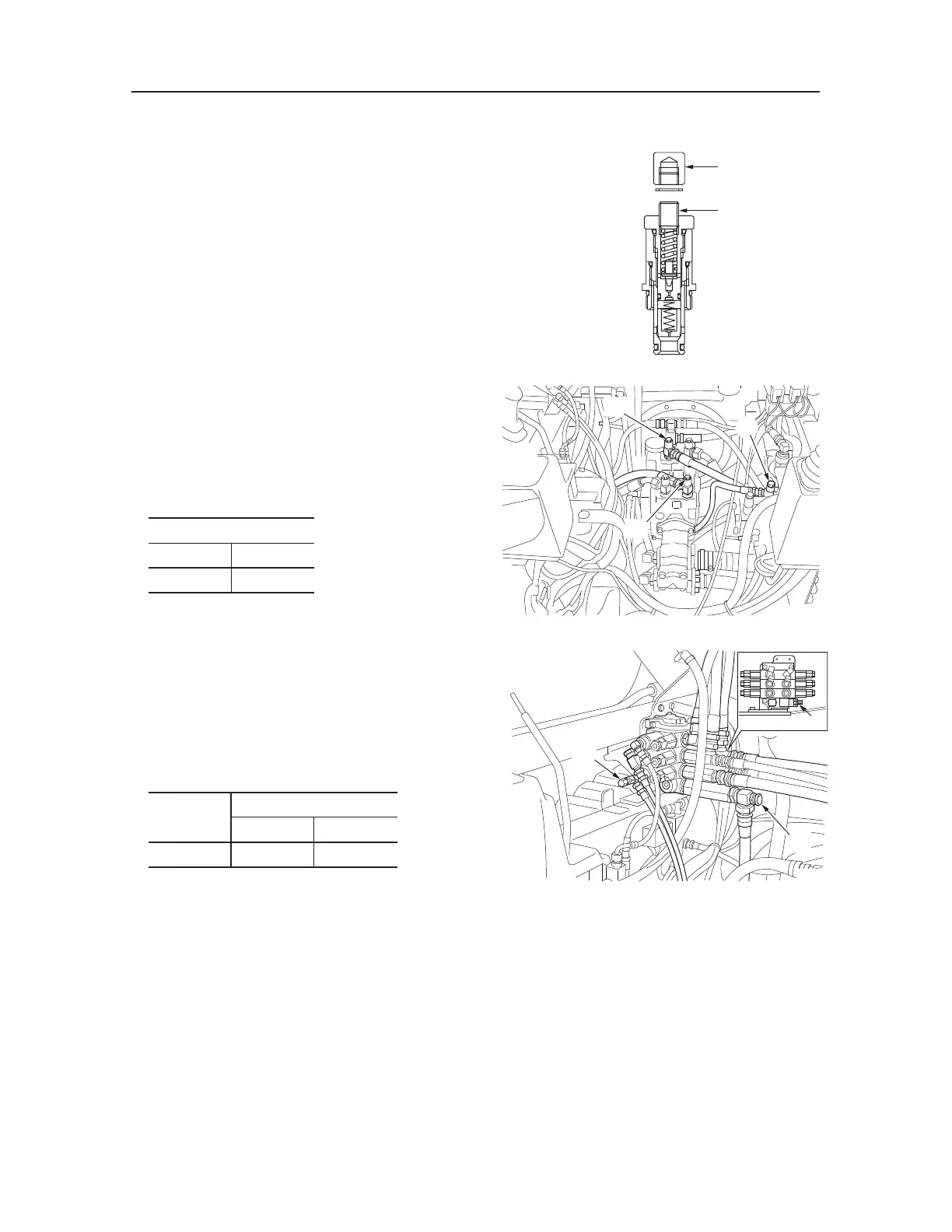
Adjusting Method
1. Loosen locknut (2), then begin adjusting pres
-
sure by turning setting screw (1).
Turning clockwise ............... raises the set pressure.
Turning counterclockwise ...
lowers the set pressure.
2. In order to keep the setting screw from turning
after pressure has been adjusted, tighten the
locknut while at the same time holding the set-
ting screw firmly in place.
3. Operate the relief valve once more to confirm
that the pressure that has been set it stabilized.
Charge pressure
Measuring Method
• Engine : Idling/Maximum R.P.M.
• Hydraulic Oil Temp. : 50~60˚C
• Insert the pressure gauge into the pressure detec
-
tion port to measure the charge pressure.
Pressure Detection Port
Port Position
Size
CG1/4
Measuring the pilot pressure
Measuring Method
• Engine : Maximum R.P.M.
• Hydraulic Oil Temp : 50~60˚C
• Mount the pressure gauge on the pressure detec
-
tion port, operate the desired hydraulic circuit and
measure the pilot pressure.
Circuit
Pressure Detection Port
Port Position
Size
Bucket dump
P4 G1/4
T7B007
C
P1
P2

 Loading...


