III-64
System Operation
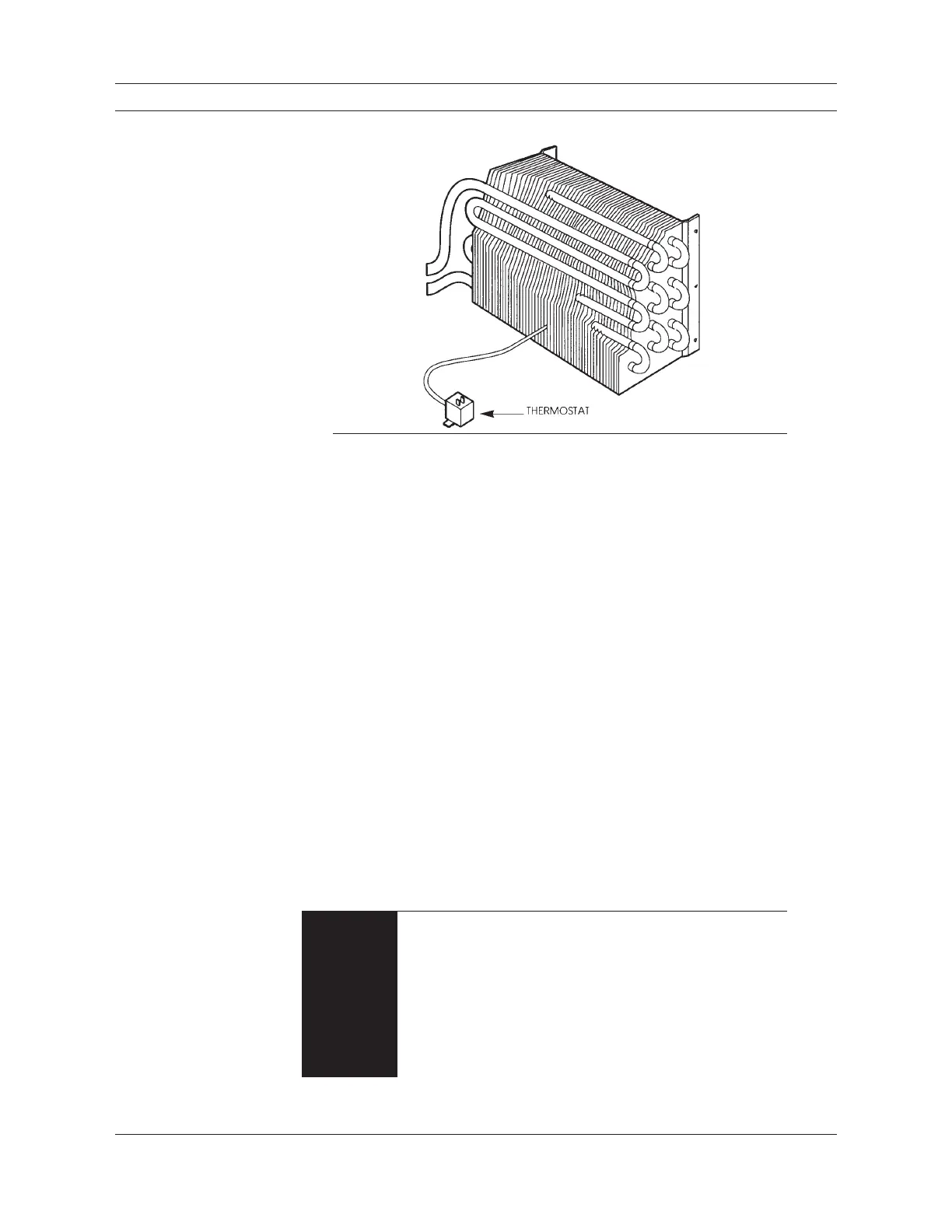
Figure 2-8
The evaporator coil as
shown is of fin and tube
construction. The thermostat
probe is positioned in
between the evaporator fins
and senses the temperature.
Note: Moisture in the air (humidity) condenses on the fins of the evapo-
rator as water droplets which drain out of the evaporator through
a drain hose. This action dehumidifies the air in the cab as part of
system operation, and contributes to operator comfort.
Cab air forced across the evaporator coil gives up heat energy to the cold refrig-
erant inside the coil. The cooled air circulates in the cab for occupant comfort.
Refrigerant continues to expand and absorb heat energy in the evaporator coil.
Refrigerant changes from liquid to gas before it leaves the evaporator on the way
back to the compressor. The refrigerant gas moves to the compressor through a
low pressure (suction) hose. When the compressor is operating, it sucks the re-
frigerant gas back inside, compressing and raising its temperature and pressure.
Some of AC system operation is controlled by the operator, and some is automatic.
The operator can turn the system on and off, regulate the air velocity with the blower
control, and in some designs adjust the thermostat control. The system and component
operating range settings automatically cycle the clutch on and off. The operation of
the expansion valve or other refrigerant metering device at the inlet to the evaporator
is automatic.
Individual system features may differ, but the basic system function remains the
same. Variations in components and controls are described in Chapters 4 and 5. The
engine provides the power for both air conditioner and heater operation. It drives the
AC compressor and the cooling system water pump. Engine RPM affects the efficiency
of both the heater and air conditioner. The slower the engine RPM, the less capacity a
heater or AC system will have.
When an AC system is operating, the high pressure side com-
ponents, fittings and high pressure lines or hoses can be hot
enough to burn your skin if you touch them. This includes the
compressor, clutch, hoses, condenser, receiver-drier, and any
control devices or metal tubing. The low pressure side will be
cool to the touch. In operation the AC system is under load
and high side pressures normally range between 150 and 250
pounds per square inch for R-12 and higher for some other
refrigerants.
WARNING

 Loading...


