IV-66
HYDRAULIC UNITS
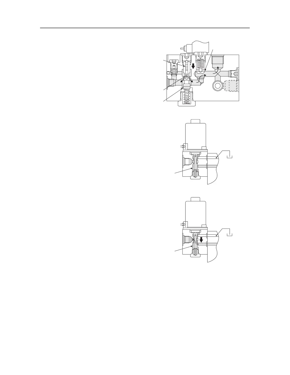
CONTROL VALVE (SUB)
The hydraulic oil from the port 1 flows through the
bore on the side panel of the spool (11) and through
the wire clearance into the chamber D, which consists
of the spool (11) and piston (12). When the pressure
in the chamber D becomes higher than the set pres-
sure, the spool (11) moves downward, releasing the
oil from the port 1 to port 2, keeping the pressure in
the port 1 at the set pressure.
The hydraulic oil in the port 2 pushes up the poppet
(5) and flows into the port 3.
When the solenoid B is not electrified
The hydraulic oil from the port P is shut off by the
spool (13).
The port 1B is connected with the port T.
When the solenoid B is electrified
The magnetic field is generated around the coil that
causes the push rod to be pulled downward, push-
ing the spool (13) downward. Then the hydraulic oil
flows from the port P to port 1B, shutting off the
circuit to the port T.
T7D905
3
5
P
2
12
D
11
T7D906
13
1B
P
T7D907
13
1B
P

 Loading...


