III-62
System Operation
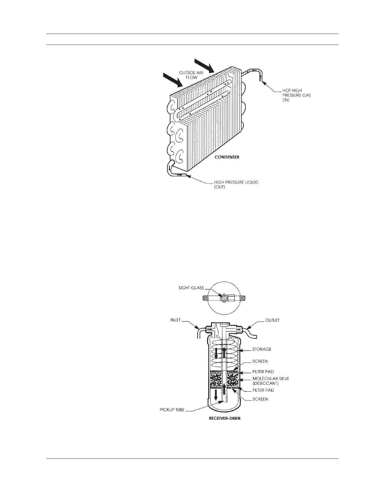
3. Receiver-Drier
The liquid refrigerant continues to move inside the system, out of the condenser
through a tube or hose to the receiver-drier. The receiver-drier serves as a small stor-
age tank and filter for the refrigerant. It is also a good location to mount pressure
switches and often contains a sight glass (small window) used to view activity inside
the system. The receiver-drier, Figure 2-6, also separates gas (bubbles) from the liquid
with a pick-up tube as shown in this illustration. Some receiver-driers have a spring to
preload the desiccant pack.
Figure 2-5
As the refrigerant gas moves
through the tubing coil from
top to bottom, it condenses
(changes state) into a liquid.
For ease of installation,
condenser fittings are often
routed close together.
Figure 2-6
This cutaway view of a re-
ceiver-drier shows the filter
elements, inlet, outlet and
refrigerant path. The sight
glass is a small window into
the system used in diagnosis
and when adding refrigerant
(charging the system).

 Loading...


