IV-50
HYDRAULIC UNITSCONTROL VALVE
G4D223
DISASSEMBLY AND ASSEMBLY
General Cautions
• Since all parts in control valves are precision
machined, carry out disassembly and assembly
operations in a clean place.
• Before disassembly, clean the outside surfaces
around the valves.
• Clean each of the disassembled parts and apply
clean hydraulic oil to them.
• Apply hydraulic oil to sliding surfaces and apply
a thin coating of grease to seals when assembling
them.
• Replace all seals with new ones each time the
valves are disassembled.
• Spools and section bodies are specially selected
for a precise fit. Therefore, if any damage is found
in either of these parts, replace the section assem-
bly as a unit.
• Be sure to number each section and spool to avoid
mistakes during assembly.
Following is an explanation of the control valve dis-
assembly procedure.
Follow the procedure used to disassemble the con-
trol valve in reverse order when reassembling it.
Disassembly
Valve Assembly
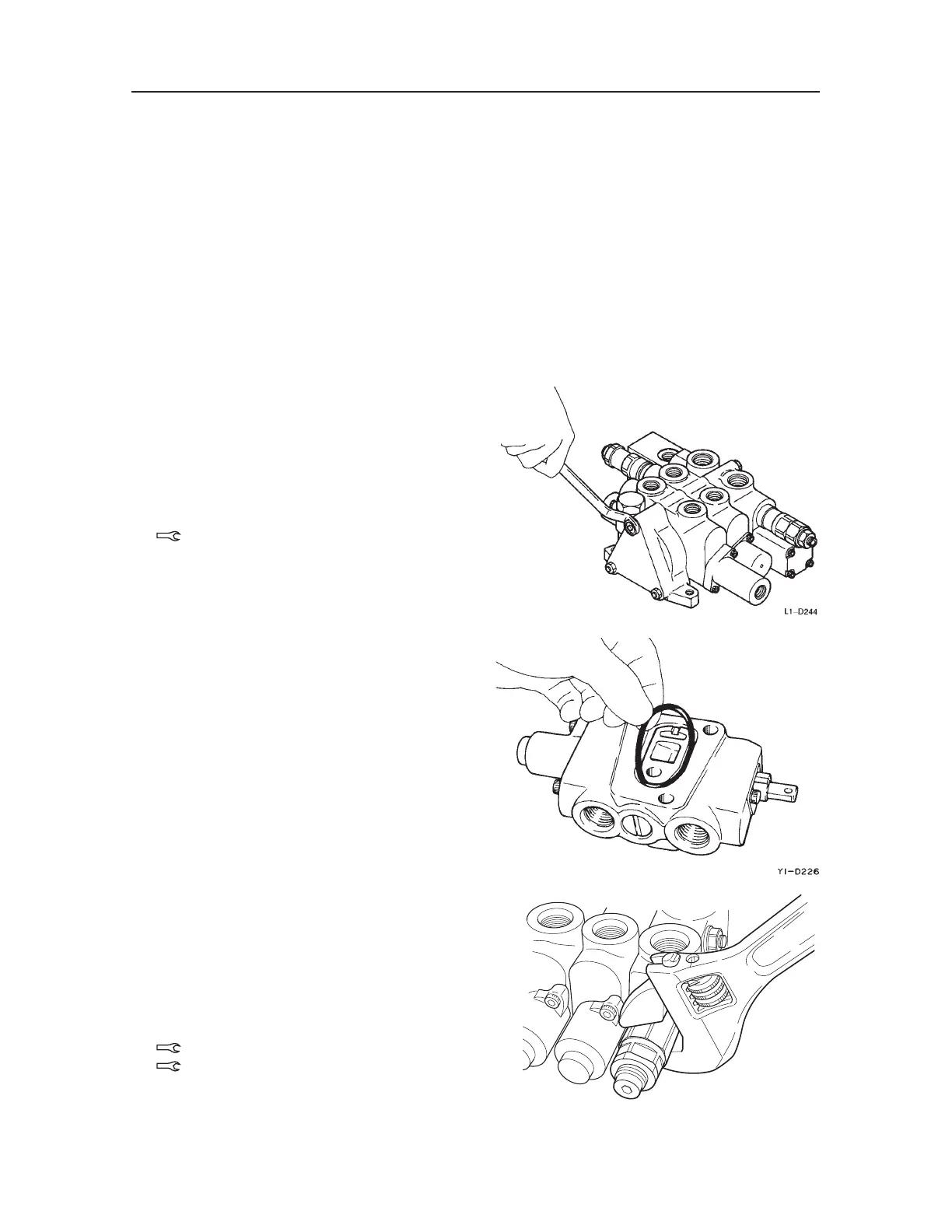
1. Loosen the nuts and remove the tie rods, then
remove the sections.
Nut: 39.23 ±3.92 N·m
2. Remove the O-ring.
• The mating surfaces are metal seals, so be
careful not to scratch, bruise or otherwise
damage them.
3. Remove the main relief valves and the port relief
valves, then remove the O-rings from the relief
valves.
• Do not disassemble the relief valves unless it
is necessary.
• When using a spanner or adjustable wrench,
be sure to attach it in the place shown in the
figure at right.
Main relief valve: 58.84 ±5.88 N·m
Port relief valve: 39.23 ±3.92 N·m

 Loading...


