EasyManuals Logo

Takeuchi TL150 Workshop Manual

Takeuchi TL150
312 pages
To Next Page IconTo Next Page
To Previous Page IconTo Previous Page
Page #164 background imageLoading...
Page #164 background image
IV-18
HYDRAULIC UNITS
HST PUMP
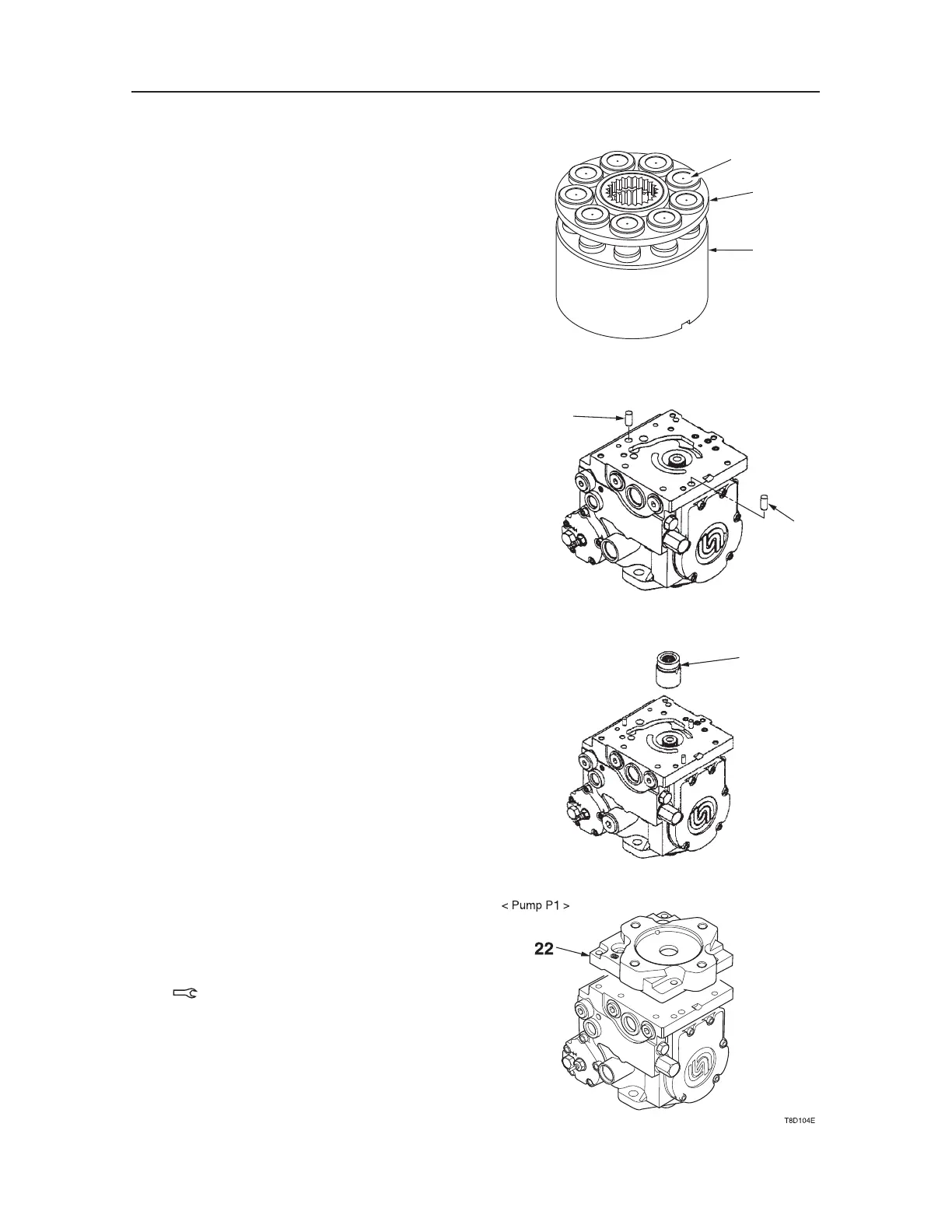
d. Insert the pistons (31) in the retainer (32), and
install them to the cylinder block (36).
Make sure that individual components are
assembled in place.
4. Install the positioning pins (29).
5. Install the drive coupling (27).
6. Install the B pad adapter (on the side of the hy
-
draulic pump P1) as follows:
a. Install the O-rings.
b. Install the B pad adapter (22), and tighten it
with the six cap screws.
Cap Screw: 36~43 N·m
S3F323
31
32
36
T7D105
29
29
S3F317
27

Table of Contents

Other manuals for Takeuchi TL150

Questions and Answers:

Question and Answer IconNeed help?

Do you have a question about the Takeuchi TL150 and is the answer not in the manual?

Takeuchi TL150 Specifications

General IconGeneral
Travel Speed - High11.2 mph (18 km/h)
Max Travel Speed12.4 km/h
Width1880 mm
Height2320 mm
Lift Height10.5 ft (3.2 m)

Related product manuals