IV-13
HYDRAULIC UNITSHST PUMP
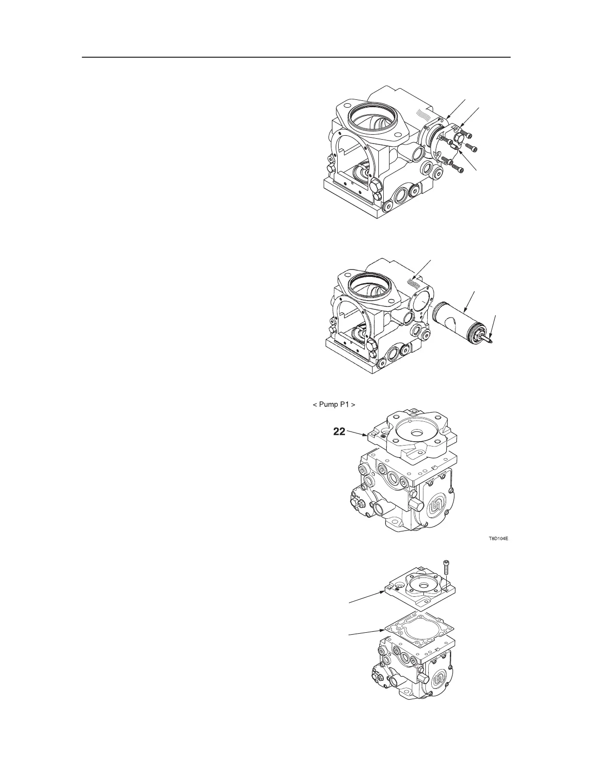
14. Remove the servo cover (19).
a. Remove the five cap screws.
b. Remove the servo cover (19) and the gasket
(17).
c. Remove the servo cover (19) from the tie bolt
(16).
15. Remove the servo piston (20).
16. Remove the B pad adapter (on the side of the
hydraulic pump P1).
a. Remove the six cap screws, and take out the
B pad adapter (22).
• If the adapter is hard to remove, slightly
tap on the adapter with a rubber hammer.
b. Remove the O-rings.
17. Remove the A pad adapter (on the side of the
hydraulic pump P2).
a. Remove the seven cap screws, and take out
the A pad adapter (24).
• If the adapter is hard to remove, slightly
tap on the adapter with a rubber hammer.
b. Remove the gasket (23).
S3F313
17
19
16
S3F314E
20
16
Mark
S3F316E
24
23
< Pump P2 >

 Loading...


