III-45
MACHINE CONFIGURATION
ATTACHMENTS
3. Remove the lift arm stopper (2).
“III-28~28-2”
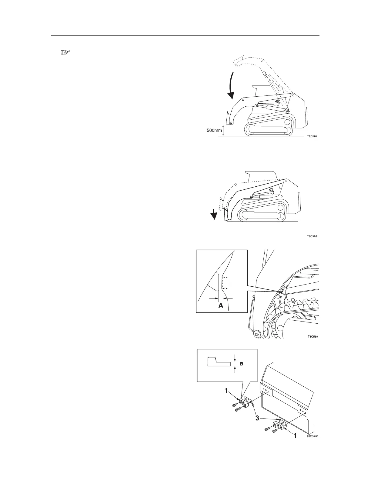
4. Start the engine, and lower the lift arm.
• The lift arm must be positioned at the height
of approximately 500 mm above the ground.
5. Press the float switch of the right control lever to
lower the lift arm, and stop the engine.
6. Measure and take note of the clearance A on the
right and the left side.
7. Install the stopper (1) and the shim (3) to each
of the right and left frames, and fasten them with
the Allen bolts.
• The shim must be such that the thickness of
the section B (27 mm thick) of the stopper (1)
plus the shim is one millimeter larger than the
clearance A measured in Step 3.
• Make sure that the lift arm presses against the
right and left stoppers at the same time.
• Allen bolts: Apply the thread-locking com
-
pound (ThreeBond #1324).
• Allen bolt tightening torque: 476 N·m

 Loading...


