Final Optimization and Test
To optimize motor shaft performance and optimize the frequency converter for the connected motor and in-
stallation, please follow these steps. Ensure that frequency converter and motor are connected and that power
is applied to frequency converter.
Before power up ensure that connected equipment is ready for use.
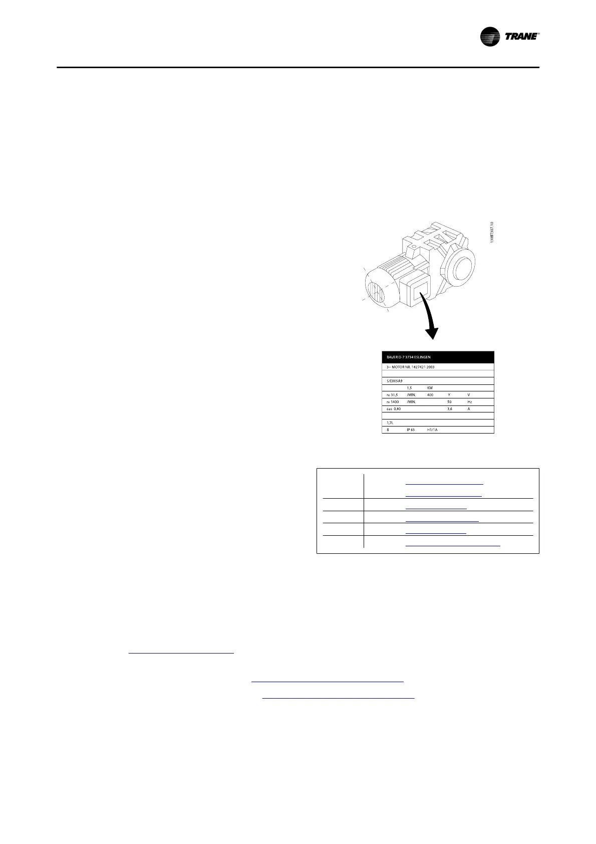
Step 1: Locate motor name plate
The motor is either star- (Y) or delta- connected (Δ). This
information is located on the motor name plate data.
Figure 4. 53: Motor name plate example
Step 2: Enter motor name plate data in following pa-
rameter list
To access list first press [QUICK MENU] key then se-
lect “Q2 Quick Setup”.
1. Par. 1-20
Motor Power [kW]
Par. 1-21
Motor Power [HP]
2. Par. 1-22
Motor Voltage
3. Par. 1-23
Motor Frequency
4. Par. 1-24
Motor Current
5. Par. 1-25
Motor Nominal Speed
Table 4. 11: Motor related parameters
Step 3: Activate Automatic Motor Adaptation (AMA)Activate Auto Tune
Performing AMA ensures best possible performance. AMA automatically takes measurements from the specific
motor connected and compensates for installation variances.
1. Connect terminal 27 to terminal 12 or use [QUICK MENU] and "Q2 Quick Setup" and set Terminal 27
par. 5-12
Terminal 27 Digital Input to
No function [0]
2. Press [QUICK MENU], select "Q3 Function Setups", select "Q3-1 General Settings", select "Q3-10 Adv. Motor
Settings" and scroll down to par. 1-29
Automatic Motor Adaptation (AMA) Automatic Motor Adaption.
3. Press [OK] to activate the AMA par. 1-29
Automatic Motor Adaptation (AMA).
4. Choose between complete or reduced AMA. If sine wave filter is mounted, run only reduced AMA, or remove
sine wave filter during AMA procedure.
Electrical Installation
BAS-SVX19C-EN 4-37