[7] ETR warning 3
[8] ETR trip 3
[9] ETR warning 4
[10] ETR trip 4
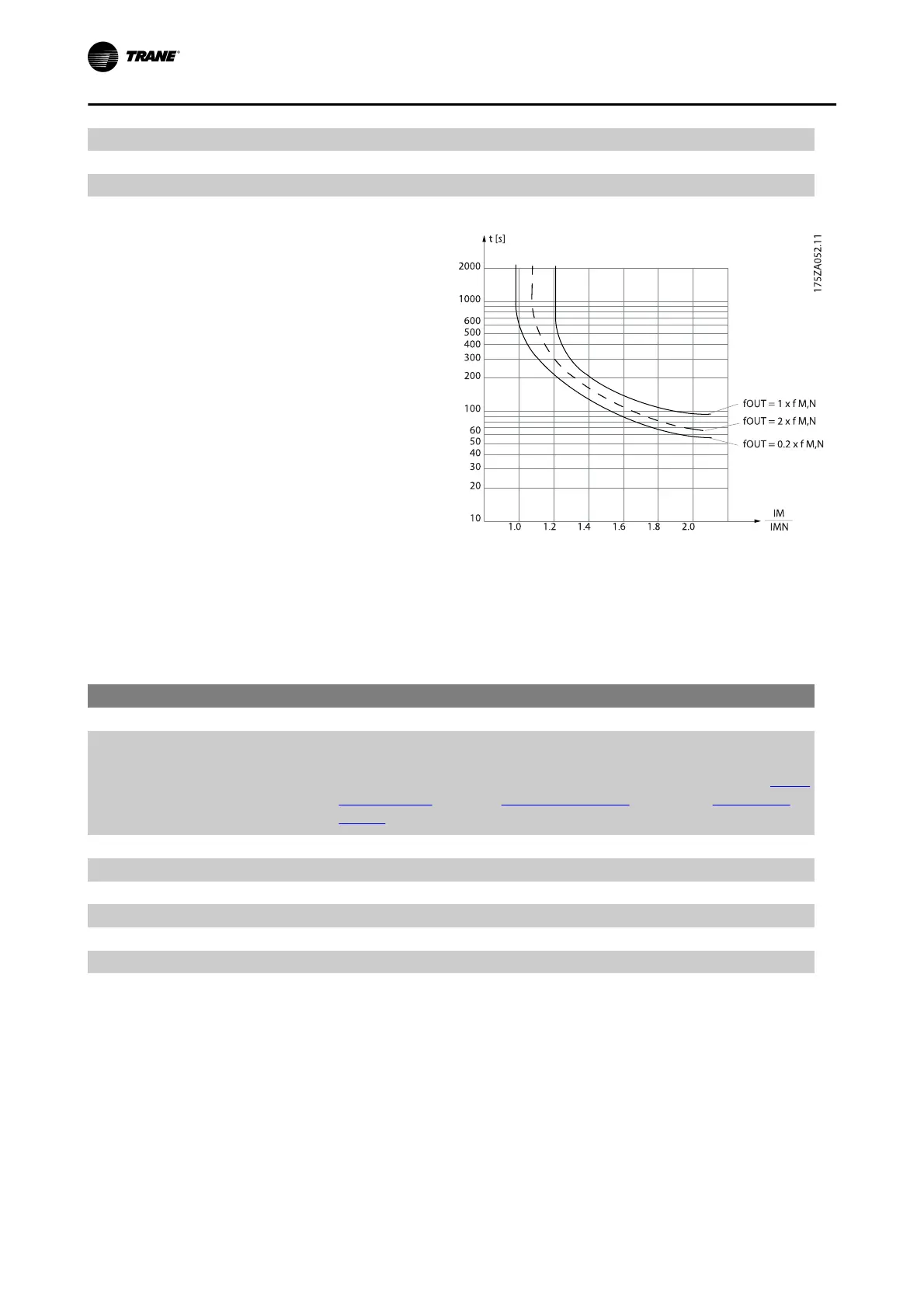
ETR (Electronic Thermal Relay) functions 1-4 will cal-
culate the load when set-up where they were selected
is active. For example ETR-3 starts calculating when
set-up 3 is selected. For the North American market:
The ETR functions provide class 20 motor overload
protection in accordance with NEC.
In order to maintain PELV, all connections made to the control terminals must be PELV, e.g. thermistor must be rein-
forced/ double insulated
Trane recommends using 24 VDC as thermistor supply voltage.
1-93 Thermistor Source
Option: Function:
Select the input to which the thermistor (PTC sensor) should be connec-
ted. An analog input option [1] or [2] cannot be selected if the analog
input is already in use as a reference source (selected in par. 3-15
Refer-
ence 1 Source, par. 3-16 Reference 2 Source or par. 3-17 Reference 3
Source).
[0] * None
[1] Analog input 53
[2] Analog input 54
[3] Digital input 18
[4] Digital input 19
[5] Digital input 32
[6] Digital input 33
NOTE
This parameter cannot be adjusted while the motor is running.
How to program the Frequency Converter
6-26 BAS-SVX19C-EN