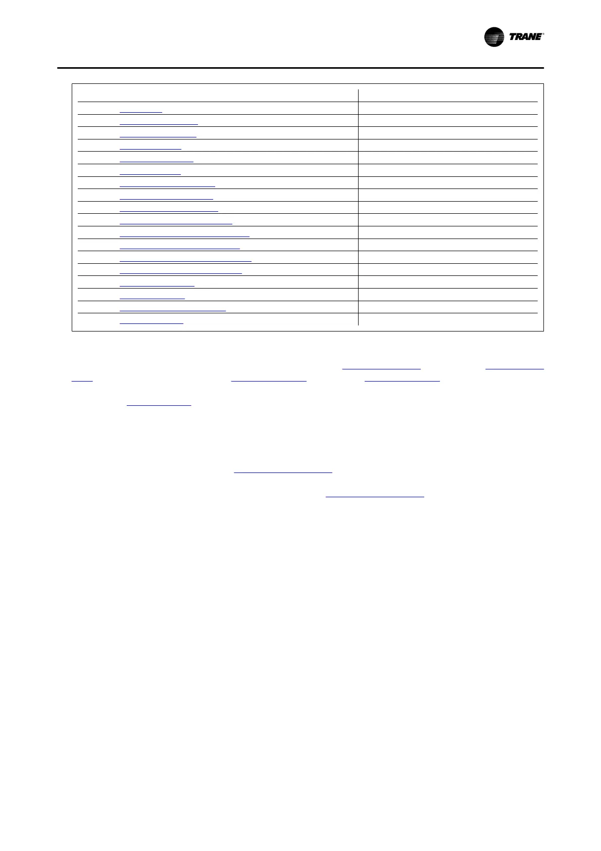
Parameter [Units]
Par. 0-01
Language
Par. 1-20
Motor Power [kW] [kW]
Par. 1-21
Motor Power [HP] [HP]
Par. 1-22
Motor Voltage*[V]
Par. 1-23
Motor Frequency [Hz]
Par. 1-24
Motor Current [A]
Par. 1-25
Motor Nominal Speed [RPM]
Par. 1-28
Motor Rotation Check [Hz]
Par. 3-41
Ramp 1 Ramp up Time [s]
Par. 3-42
Ramp 1 Ramp Down Time [s]
Par. 4-11
Motor Speed Low Limit [RPM] [RPM]
Par. 4-12
Motor Speed Low Limit [Hz]*[Hz]
Par. 4-13
Motor Speed High Limit [RPM] [RPM]
Par. 4-14
Motor Speed High Limit [Hz]*[Hz]
Par. 3-19
Jog Speed [RPM] [RPM]
Par. 3-11
Jog Speed [Hz]*[Hz]
Par. 5-12
Terminal 27 Digital Input
Par. 5-40
Function Relay**
Table 6. 1: Quick Setup parameters
*The display showing depends on choices made in par. 0-02 Motor Speed Unit and par. 0-03 Regional Set-
tings. The default settings of par. 0-02 Motor Speed Unit and par. 0-03 Regional Settings depend on which region
of the world the frequency converter is supplied to but can be re-programd as required.
** Par. 5-40
Function Relay, is an array, where one may choose between Relay1 [0] or Relay2 [1]. Standard
setting is Relay1 [0] with the default choice Alarm [9].
See the parameter description in the section
Commonly Used Parameters
.
For a detailed information about settings and programming, please see the
TR200 Programming Guide
If [No Operation] is selected in par. 5-12 Terminal 27 Digital Input, no connection to +24 V on terminal 27 is necessary
to enable start.
If [Coast Inverse] (factory default value) is selected in par. 5-12
Terminal 27 Digital Input, a connection to +24V is
necessary to enable start.
How to program the Frequency Converter
BAS-SVX19C-EN 6-3