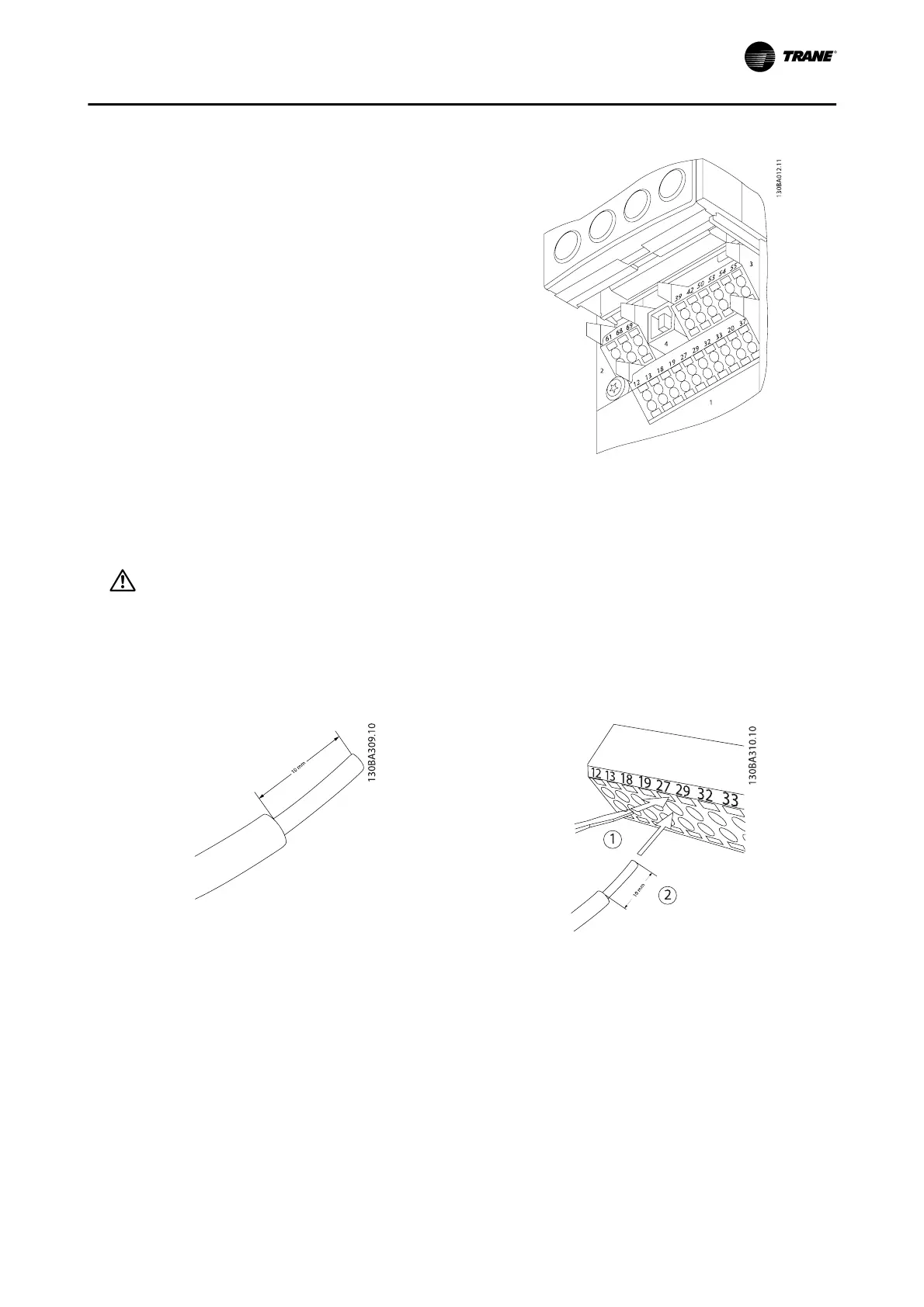
Control Terminals
Drawing reference numbers:
1. 10-pole plug digital I/O.
2. 3-pole plug RS-485 Bus.
3. 6-pole analog I/O.
4. USB connection.
Figure 4. 42: Control terminals (all enclosures)
How to Test Motor and Direction of Rotation
WARNING
Unintended motor start could occur. Follow proper lockout/tagout procedures to ensure the power cannot be inadver-
tently energized. Stay away from rotating components to avoid being injured. Failure to follow recommendations could
result in death or serious injury.
Please follow these steps to test the motor connection and direction of rotation. Start with no power to the unit.
Figure 4. 43:
Step 1: First remove the insulation on both ends of a
50 to 70 mm piece of wire.
Figure 4. 44:
Step 2: Insert one end in terminal 27 using a suitable
terminal screwdriver.
Electrical Installation
BAS-SVX19C-EN 4-33