TITANUS
MICRO·SENS
®
Installation
06/13
107
WARNING
Carry out all connection work to the device with the power off!
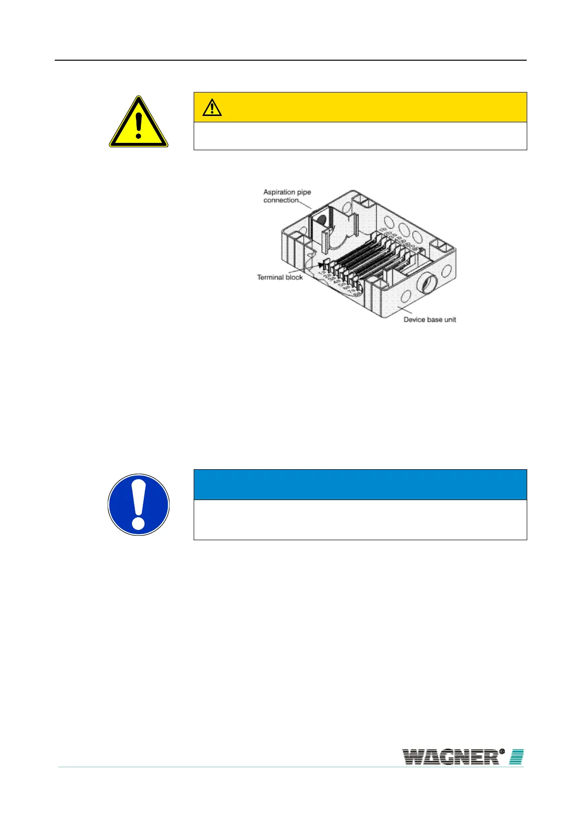
Figure 64: Arrangement of screw terminals in the device base unit
Alarm and fault contact can be used, for example, to connect to a FAS or to
control signals, guidance systems etc. There is also the option of connecting
a parallel display or reaction indicators to the device indicator bus.
NOTICE
Permanent wiring in the reset input leads to all messages being automati-
cally reset when the cause of the message has been removed.
If additional modules or a parallel display are used, then an installation plate
is screwed into the base unit of the additional housing.
dditional housing

 Loading...