Installation
TITANUS
MICRO·SENS
®
106
06/13
Incorporation and electrical connection of
additional modules
To prepare the electrical connections, the following steps must first be taken:
1. Make the number of cable entries required on the device base unit, e.g.
with a screwdriver.
2. Put the cable entries M20 and/or M25 into the corresponding cable
holes.
3. Feed the cable through the corresponding cable holes.
NOTICE
2x M20 and 1x M25 cable entries are supplied with the device.
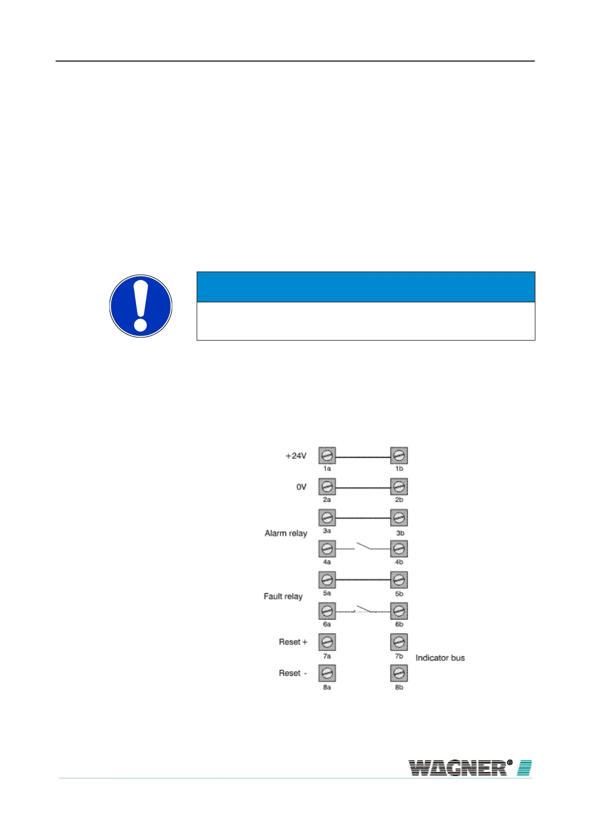
The electrical connection is made via screw terminals 1a to 8a and 1b to 8b
on the TITANUS
MICRO·SENS
®
base unit. In so doing, note the permitted
cable cross-sections on the threaded joints and the permitted wire cross-
sections on the terminals for a max. 0.5 mm² - 2.5 mm² wires.
Figure 63: Layout of screw terminals in the device base unit
6.3

 Loading...
