TITANUS
MICRO·SENS
®
Installation
06/13
125
4. Refit the detection unit by using a screwdriver to screw the four screws
on the detection unit of the device cover down firmly.
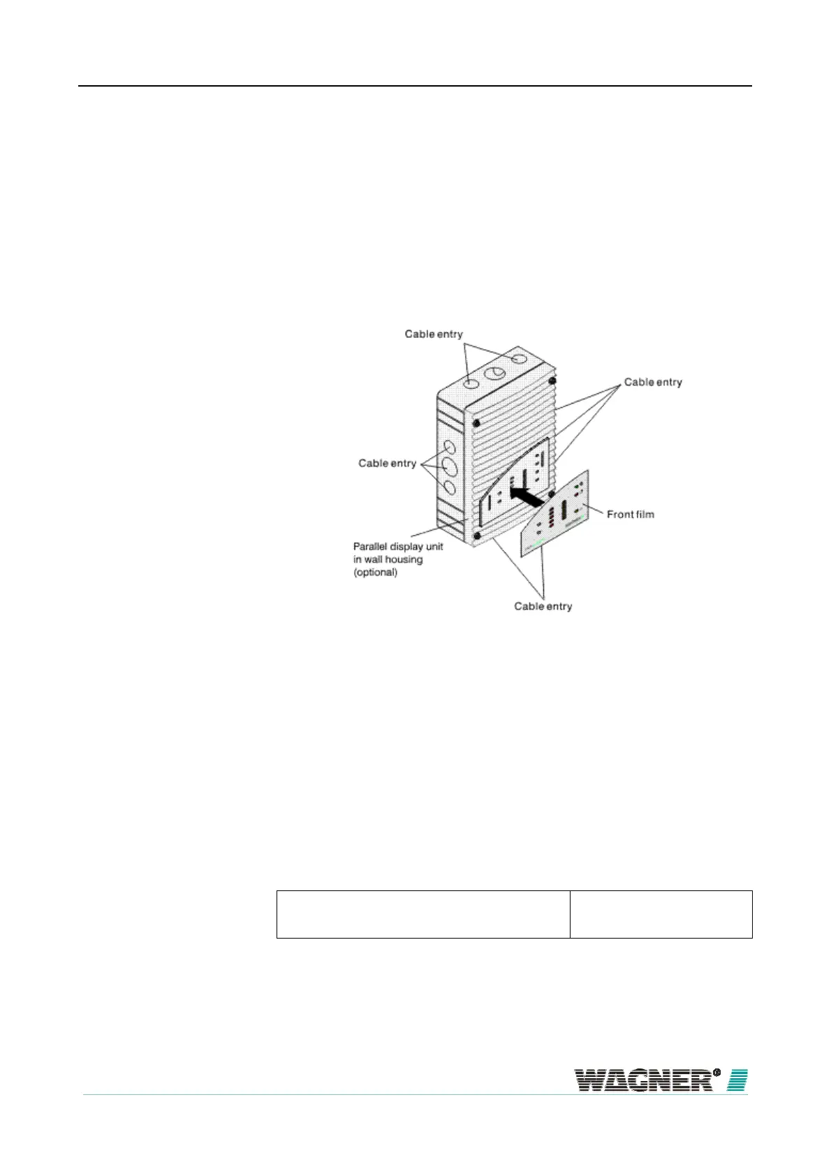
Remote display housing
Fitting the front film
Figure 79: Fitting the front film for the remote display
With the remote display the cable entry can be above, below or at the side
without the cover having to be turned. The switching power supply for the
remote display is fitted to the installation plate of the remote display housing
(for fixing points see Figure "Arrangement of holes on the installation plate of
the additional housing").
The device base unit for a parallel display is screwed directly onto a wall.
Parallel display Cylinder or flat head screws
– Thread diameter: max. 4 mm
– Head diameter: max. 8 mm
The drilling template is shown in this chapter for assembly / installation (all
dimensions in mm).
6.9.2
Wall fixing
Installation equipmen
Hole distances

 Loading...
