Installation
TITANUS
MICRO·SENS
®
126
06/13
Electrical connection
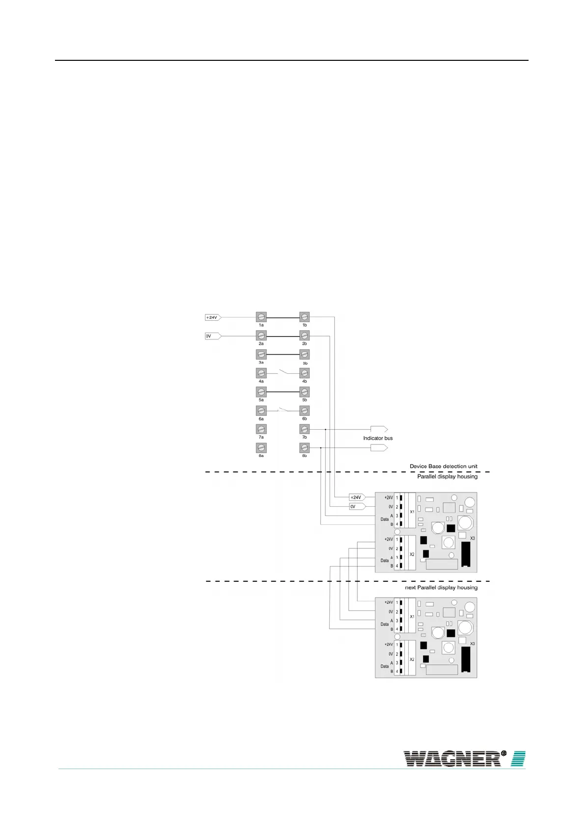
Connect the remote displays via the terminal block 7b and 8b indicator bus
on the device base unit of the TITANUS
MICRO·SENS
®
. The power is sup-
plied via TITANUS
MICRO·SENS
®
or for greater distances, externally. Cal-
culate the lines as for TITANUS
MICRO·SENS
®
, in accordance with Chapter
Design "Power Supply".
You must comply with the permitted cable cross-sections for the particular
cable throughputs and the permitted wire cross-sections for the terminals
(see Chapter "Technical Data ").
Connect the remote display to the TITANUS
MICRO·SENS
®
with the power
off as follows:
Figure 80: Connecting the parallel display to TITANUS MICRO·SENS
®
6.9.3
Remote displa

 Loading...
