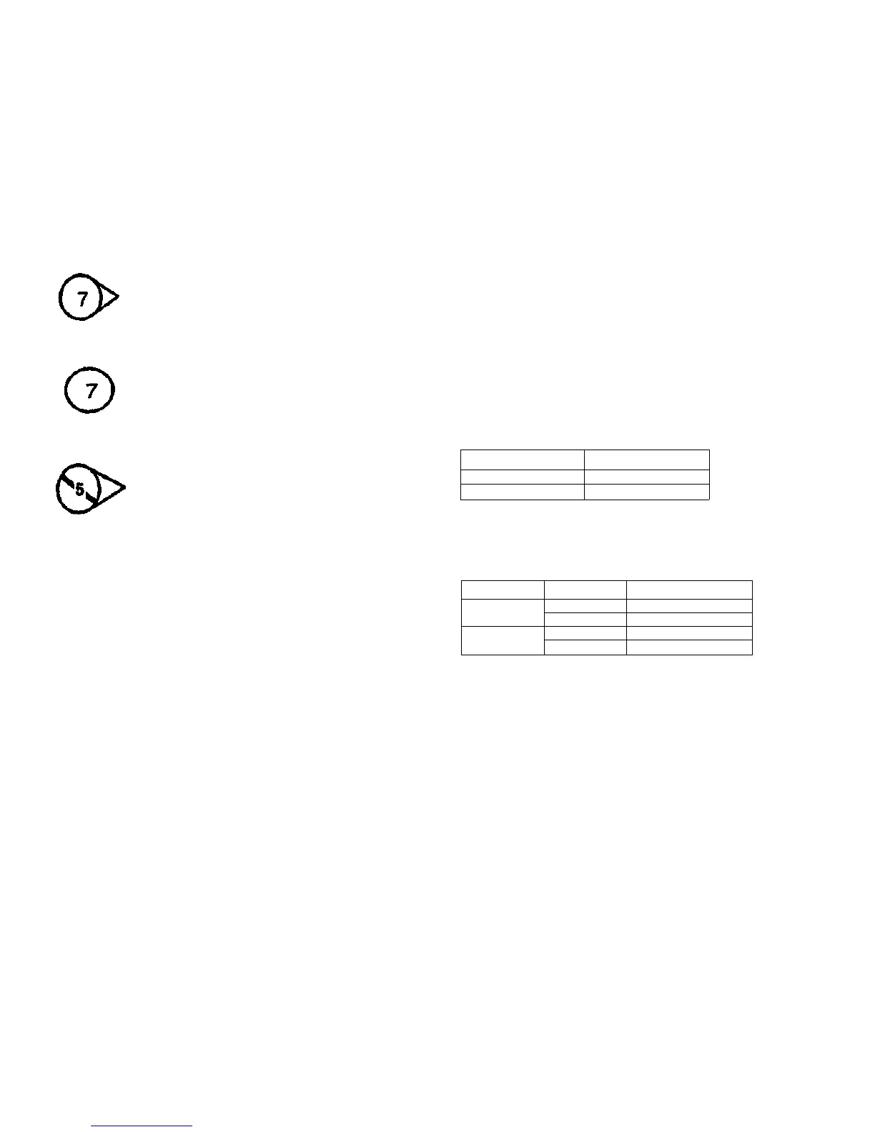
Tag / MOD Information
This symbol indicates that the area to which the triangle points has been mod-
ified by the tag number in the circle.
This symbol identifies the component or configuration of components in a
circuit diagram that are not part of a change identified with this Tag / MOD
number.
Signal Nomenclature
The signal is named to imply the condition of the machine when the signal is available. For
example:
MAIN MOTOR ON (L) +5 VDC
1. MAIN MOTOR ON = Signal Name
2. (L) = Logic State whan the signal is available in it's named state. In this case, the signal is
Low when the Main Motor Is energized.
3. +5 VDC = Logic level when the signal Is High.
DC Voltage Levels
DC Voltages should be measured between the test point and the machine frame, unless
Instructed otherwise. Table 3 shows the value of the voltages.
Table 3
Voltage
+5 VDC
+24 VDC
Specification
+4.5 to +5.5 VDC
+21.6 to +26.4 VDC
Logic Voltage Levels
Measurements of logic levels must be made with reference to the specified ground point,
unless some other point is referenced in a diagnostic procedure.
Table 4
Nominal Voltage
+5 VDC
+24 VDC
Logic State
H
L
H
L
Actual Voltage Ranges
+4.8 VDC
to
+5.2 VDC
0.0 VDC
to
+1.0 VDC
+22.0 VDC to +25.7 VDC
0.0 VDC
to
+3.0 VDC
8830 DOS
3/98
XIII
introduction
Reference Symbology
This symbol Identifies the component or configuration of components In a cir-
cuit diagram that are part of a change identified with the Tag / MOD number.
 Loading...


