67C3K11 5-38
1
2
3
4
5
6
7
8
9
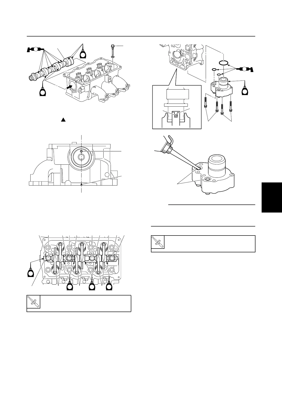
7. Align the dowel hole b in the camshaft
with the “” mark c on the cylinder
head as shown.
8. Install the rocker arms D, rocker arm
shaft E, springs F, and retainers G into
the cylinder head, and then tighten the
bolts H to the specified torque.
9. Install the oil pump assembly by aligning
the slot d in the oil pump drive shaft with
the camshaft pin I, and then tighten the
bolts J to the specified torque.
NOTE:
Before installing the oil pump assembly, be
sure to fill it with a small amount of engine oil
through the oil passages e.
T
R
.
.
Rocker arm shaft bolt H:
18 N·m (1.8 kgf·m, 13.3 ft·lb)
S67C5110
B
C
E
E
M
S67C5111
b
c
S67C5112
D
G H
E
D
G
H
F
F
G
G
HH
D
E
E EE
T
R
.
.
Oil pump assembly bolt J:
8 N·m (0.8 kgf·m, 5.9 ft·lb)
S67C5114
A
d
J
J
E
I
S67C5113
e
Cylinder head