LOWR
Lower unit
6-19 67C3K11
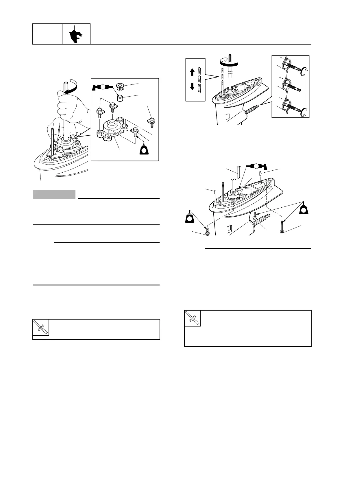
4. Install the water pump housing 8 onto
the lower case, and then install the rub-
ber spacer 9 and collar 0.
CAUTION:
Do not turn the drive shaft counterclock-
wise, otherwise the water pump impeller
may be damaged.
NOTE:
• Apply grease to the inside of the water
pump housing 8.
• While turning the drive shaft clockwise,
push down on the water pump housing 8
and install it.
5. Tighten the water pump housing bolts A
to the specified torque.
Installing the lower unit
1. Set the shift lever to the N position. (H
model)
Set the remote control lever to the N
position. (R model)
2. Set the shift rod to the N position.
3. Install the lower unit to the upper case,
and then tighten the lower case mounting
bolts 1 and 2 to the specified torque.
NOTE:
• Before installing the lower unit to the upper
case, install the dowels 3 into the lower
case.
• When installing the lower unit, make sure
that the water pipe 4 is inserted securely
into the collar 5.
4. Connect the speedometer hose 6.
5. Turn the adjusting nut 7 to connect the
shift rods 8, and then tighten the locknut
9.
T
R
.
.
Water pump housing bolt A:
18 N·m (1.8 kgf·m, 13.3 ft·lb)
S67C6056
572
LT
8
0
9
A
A
A
A
T
R
.
.
Lower case mounting bolt (M10) 1:
39 N·m (3.9 kgf·m, 28.8 ft·lb)
Lower case mounting bolt (M8) 2:
18 N·m (1.8 kgf·m, 13.3 ft·lb)
S67C6057
F
N
R
F
N
R
S67C6058
1
2
1
3
3
4
A
5
572
LT
572
LT