ELEC
Electrical system
– +
8-19 67C3K11
2. Check the engine shut-off switch 1 for
continuity between the engine shut-off
switch connector and ground terminal
(engine shut-off switch end). Replace if
out of specification.
3. Connect the engine shut-off switch con-
nector and ground terminal.
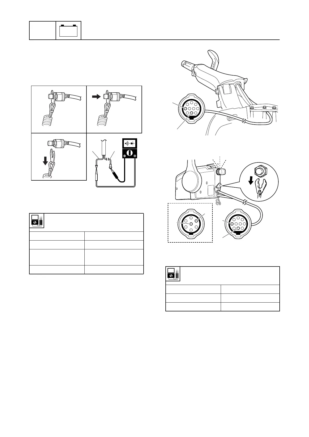
Checking the engine shut-off switch
(E and W model)
1. Disconnect the 10-pin (7-pin) main har-
ness coupler.
2. Turn the engine start switch to “ON,” and
then check the engine shut-off switch for
continuity at the 10-pin (7-pin) main har-
ness coupler (tiller handle end or remote
control box end). Check the wiring har-
ness or replace the engine shut-off
switch if out of specification.
È H model
É R model
Ê 7-pin main harness model
3. Turn the engine start switch to “OFF.”
4. Connect the 10-pin (7-pin) main harness
coupler.
Engine electric control system
Checking the CDI unit
1. Disconnect the ignition coil 1 coupler.
2. Connect the special service tool 2 to the
ignition coil coupler.
Engine shut-off switch continuity:
White (W) – Black (B)
Switch position Continuity
Clip installed a No
Engine stop button
pushed b
Yes
Clip removed c Yes
S6AG8150
B
W
a b
c
Engine shut-off switch continuity:
White (W) 1 – Black (B) 2
Switch position Continuity
Clip installed No
Clip removed Yes
S67C8071
1
2
È
S67C8047
1
2
2
1
Ê
OFF
ON
START
É