67C3K11 8-20
1
2
3
4
5
6
7
8
9
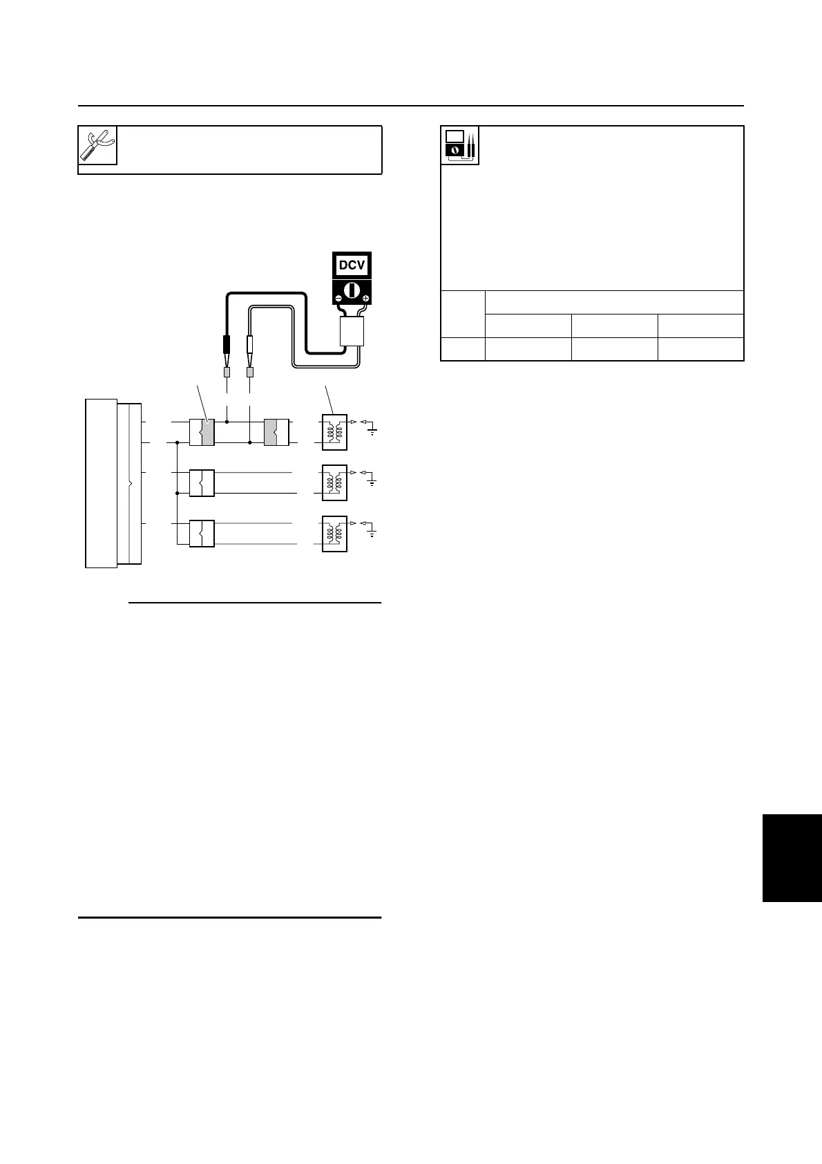
3. Measure the CDI unit 3 output peak
voltage. Replace if below specification.
NOTE:
• To prevent the engine from starting when
cranking it, be sure to disconnect all spark
plug caps.
• Do not remove the clip from the engine
shut-off switch.
• When using the manual starter to crank the
engine to measure the output peak voltage,
turn the engine start switch to “ON” (W
model).
• When using the manual starter to crank the
engine, the voltage values may vary
depending on the speed at which the
starter handle is pulled.
• Be sure to check the charge coil and pulser
coil before measuring the CDI unit output
peak voltage.
4. Disconnect the special service tool 2
and connect the ignition coil coupler.
Test harness (2 pins) 2:
90890-06867
S67C8048
B/O
O
B/O
O
B/W
O
B/W
B/Y
O
B/Y
15
16
13
14
G/WG
2
3
1
#1
#2
#3
CDI unit output peak voltage
(reference data):
#1: Orange (O) –
Black/orange (B/O)
#2: Orange (O) –
Black/white (B/W)
#3: Orange (O) –
Black/yellow (B/Y)
r/min
Loaded
Cranking 1,500 3,500
DC V 120 170 170
Ignition and ignition control system / Engine electric control system



 To Next Page