POWR
Power unit
5-47 67C3K11
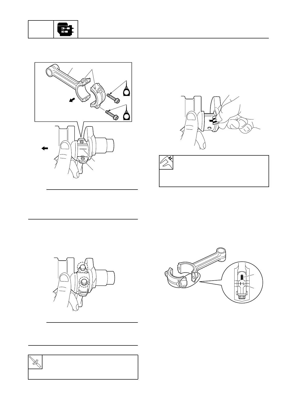
3. Install the connecting rod 1 and bear-
ings to the crankpin 2.
NOTE:
Make sure that the projections a on the con-
necting rod and connecting rod cap face
towards the flywheel magnet end È of the
crankshaft.
4. Tighten the connecting rod cap bolts to
the specified torques in 2 stages.
NOTE:
Do not turn the connecting rod until the
crankpin oil clearance measurement has
been completed.
5. Remove the connecting rod cap and
measure the width of the compressed
Plastigauge (PG-1) on the crankpin.
Check the connecting rods, bearings,
and crankshaft if out of specification and
replace the defective parts.
Selecting the connecting rod bearing
1. When replacing the connecting rod bear-
ing, select the suitable bearing as fol-
lows.
2. Check the connecting rod mark a or
painted color b on the connecting rod.
3. Select the suitable bearing color c for
the connecting rod bearing from the
table.
T
R
.
.
Connecting rod cap bolt:
1st: 6 N·m (0.6 kgf·m, 4.4 ft·lb)
2nd: 17 N·m (1.7 kgf·m, 12.5 ft·lb)
S67C5140
2
1
È
1
a
È
E
E
S6AU5146
Crankpin oil clearance (reference
data):
0.020–0.052 mm
(0.0008–0.0020 in)
S6AU5147
S67C5171
b
a