67C3K11 7-44
1
2
3
4
5
6
7
8
9
NOTE:
See the exploded diagram for the filter instal-
lation positions (7-39).
Assembling the gear pump
CAUTION:
• Do not use a rag when assembling the
PTT unit as dust and particles on the
PTT unit components can lead to poor
performance.
• Do not reuse the O-rings, always replace
them with new ones.
NOTE:
Lubricate the parts with ATF Dexron II during
assembly.
1. Install the valve pin seal 1, valve pin 2,
and valve lock screw 3 into the relief
valve 4.
2. Install the relief valve assembly 5, and
then tighten the valve lock screw 6 to
the specified torque.
NOTE:
Turn in the valve lock screw 3 the same
number of turns it was turned out when it was
removed.
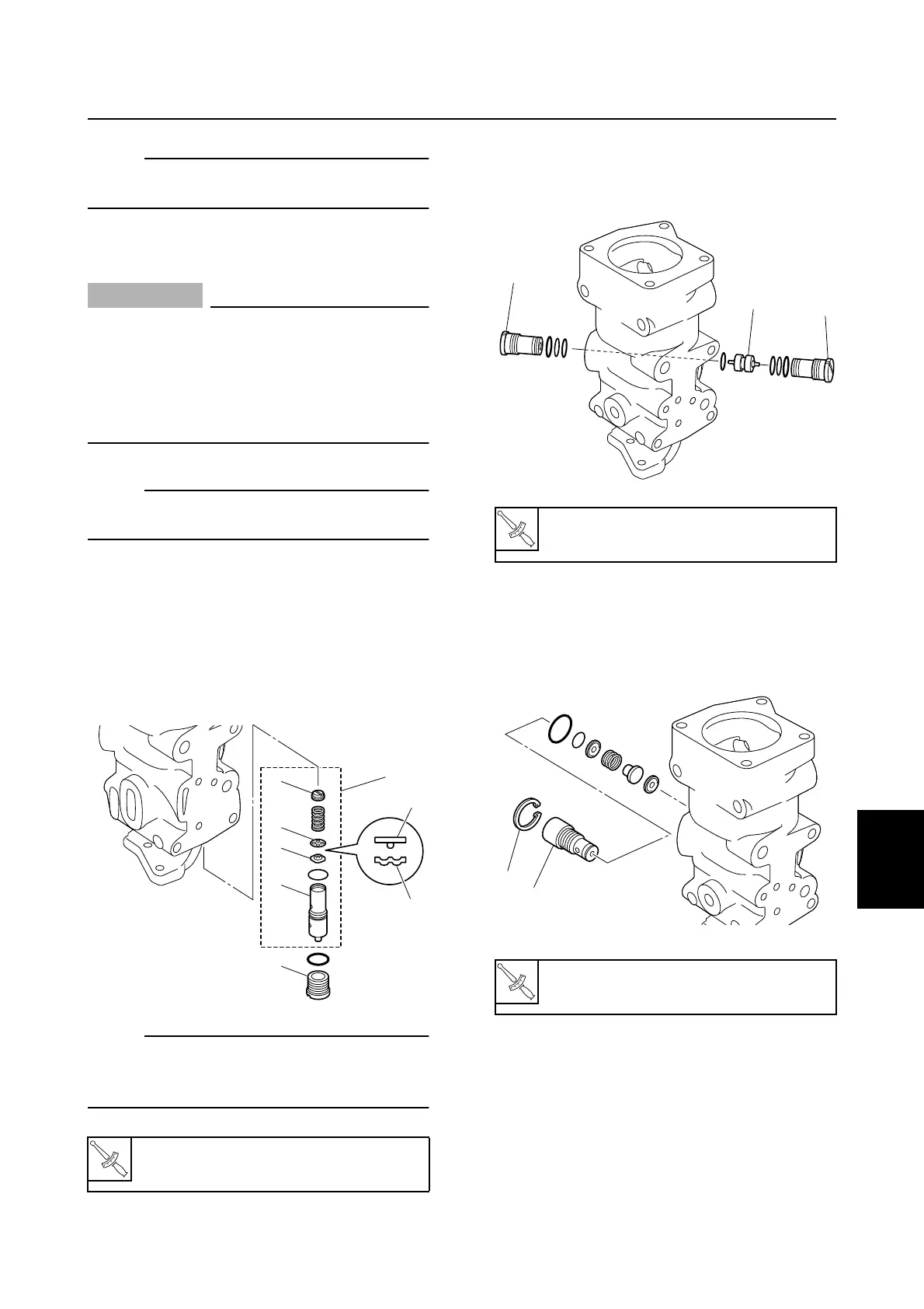
3. Install the shuttle piston 7, and then
tighten the main valves 8 to the speci-
fied torque.
4. Install the manual valve 9 and circlip 0,
and then tighten the valve to the speci-
fied torque.
T
R
.
.
Valve lock screw 6:
6 N·m (0.6 kgf·m, 4.4 ft·lb)
S67C7082
3
5
2
1
4
6
2
1
T
R
.
.
Main valve 8:
7 N·m (0.7 kgf·m, 5.2 ft·lb)
T
R
.
.
Manual valve 9:
3 N·m (0.3 kgf·m, 2.2 ft·lb)
S67C7083
8
7
8
S67C7085
0
9
PTT gear pump