67C3K11 7-52
1
2
3
4
5
6
7
8
9
NOTE:
Connect the PTT motor leads directly to the
battery terminals when the power unit is not
installed. To connect the PTT motor leads,
see “Bleeding the PTT unit” (7-50).
2. Let the fluid settle for 5 minutes with the
outboard motor tilted down.
3. Push the PTT switch to tilt the outboard
motor to the fully up position.
4. Support the outboard motor with the tilt
stop lever, and then let the fluid settle for
5 minutes.
WARNING
After tilting up the outboard motor, be
sure to support it with the tilt stop lever.
Otherwise, the outboard motor could sud-
denly lower if the PTT unit should lose
fluid pressure.
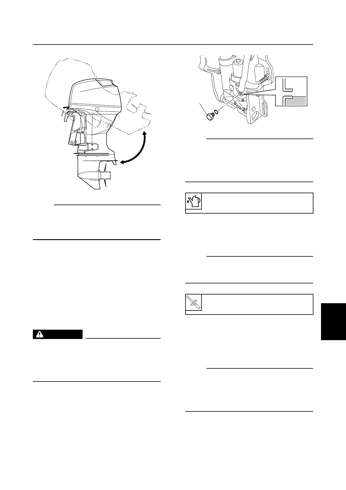
5. Remove the reservoir cap 1, and then
check the fluid level in the reservoir.
NOTE:
• If the fluid is at the correct level, a small
amount of fluid should overflow out of the
filler hole when the cap is removed.
• If the fluid is below the correct level, add the
recommended PTT fluid.
6. Install a new O-ring and the reservoir cap
1, and then tighten the cap to the speci-
fied torque.
NOTE:
If the fluid is below the correct level in step 5,
repeat steps 1–6 until the fluid remains at the
correct level.
PTT electrical system
Checking the fuse
1. Check the fuse for continuity. Replace if
there is no continuity.
NOTE:
• For the location of the fuse, see “Electrical
component and wiring harness routing” (8-
1).
• To check the fuse, see “Checking the fuse
(E and W model)” (8-13).
S67C7139
Recommended PTT fluid:
ATF Dexron II
T
R
.
.
Reservoir cap 1:
7 N·m (0.7 kgf·m, 5.2 ft·lb)
S67C3040
1
PTT cylinder / PTT electrical system