67C3K11 7-32
1
2
3
4
5
6
7
8
9
NOTE:
Install the ground lead terminals B and C as
shown.
7. Pass the PTT motor lead D through the
hole a in the clamp bracket 6 (STBD).
8. Fasten the PTT motor lead D to the
clamp bracket 6 with a plastic ties E.
9. Fasten the PTT motor lead D and trim
sensor lead F with the plastic ties G. (R
model)
10. Apply grease to the grease nipples until it
comes out from the areas b.
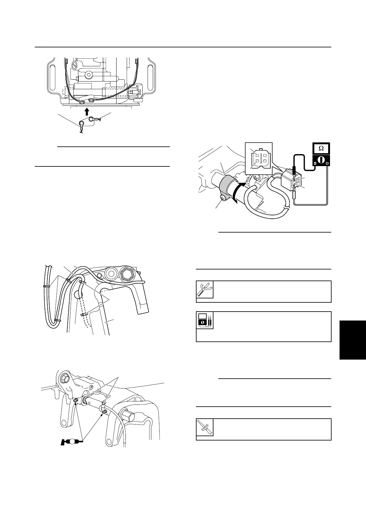
Adjusting the trim sensor cam (R
model)
1. Tilt the outboard motor to the fully down
position.
2. Loosen the trim sensor cam screw 1.
3. Adjust the trim sensor cam 2 so that the
trim sensor setting resistance is within
specification.
NOTE:
• To decrease the resistance, turn the trim
sensor cam in direction a.
• To increase the resistance, turn the trim
sensor cam in direction b.
4. Tighten the trim sensor cam screw 1 to
the specified torque.
NOTE:
Check the trim sensor setting resistance
again after tightening the trim sensor cam
screw 1.
S67C7056
C
B
S67C7144
D
G
F
6
E
a
S67C7058
A
b
Digital circuit tester: 90890-03174
Trim sensor setting resistance:
Pink (P) – Black (B)
9–11 Ω at 20 °C (68 °F)
T
R
.
.
Trim sensor cam screw 1:
2 N·m (0.2 kgf·m, 1.5 ft·lb)
S67C7125
B
P
2
a
b
1
B
P
Clamp bracket and swivel bracket