POWR
Power unit
5-3 67C3K11
6. Loosen the rocker arm locknut 6, and
then turn the adjusting screw 7 until the
specified valve clearance is obtained.
NOTE:
• To decrease the valve clearance, turn the
adjusting screw 7 in direction e.
• To increase the valve clearance, turn the
adjusting screw 7 in direction f.
7. Tighten the rocker arm locknut 6 to the
specified torque.
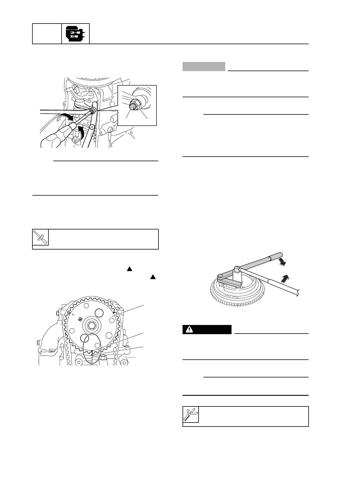
8. Turn the flywheel magnet an additional
240° clockwise and align the “” mark g
on the driven sprocket 5 with the “”
mark b on the cylinder head.
9. Repeat steps 5–7 for cylinder #2.
10. Repeat steps 8–9 for cylinder #3.
11. Install all parts removed during removal.
Replacing the timing belt
CAUTION:
Do not turn the flywheel magnet counter-
clockwise, otherwise the water pump
impeller may be damaged.
NOTE:
To remove and install the timing belt, drive
sprocket, and driven sprocket, see “Remov-
ing the timing belt and sprocket” (5-23) and
“Installing the sprocket and timing belt” (5-
24).
1. Remove the manual starter, starter hub,
and driven spocket cover. (M and W
model)
Remove the flywheel magnet cover. (E
model)
2. Disconnect the spark plug caps and
remove the spark plugs.
3. Remove the flywheel magnet nut.
WARNING
Apply force in the direction of the arrows
shown to prevent the flywheel holder from
slipping off easily.
NOTE:
Use a 30 mm socket to loosen the flywheel
magnet nut.
T
R
.
.
Rocker arm locknut 6:
14 N·m (1.4 kgf·m, 10.3 ft·lb)
S67C5006
7 6
f
e
S67C5008
g
5
b
Flywheel holder: 90890-06522
S6AG5G30