67C3K11 7-54
1
2
3
4
5
6
7
8
9
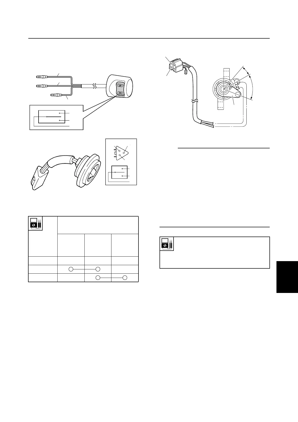
Checking the PTT switch
1. Check the PTT switch for continuity.
Replace if out of specification.
È H model
É R model
Checking the trim sensor
1. Measure the trim sensor resistance.
Adjust the trim sensor if out of specifica-
tion.
NOTE:
• Turn the trim sensor lever 1 from a to c
and measure the resistance as it gradually
changes.
• Position b is the trim sensor lever position
when the outboard motor is tilted down. To
adjust the trim sensor cam, see “Adjusting
the trim sensor cam (R model)” (7-32).
• The trim sensor resistance will be lower at
position c than at position b.
• Range d is the trim and tilt operation
range.
Lead color
Switch
position
Sky blue
(Sb)
Red (R) Light
green
(Lg)
Free
Up
Down
S67C7110
Lg
Sb
R
Lg
Sb
R
È
S67C7141
Sb R
Lg
Lg
Sb
R
É
Trim sensor resistance:
Pink (P) – Black (B)
238.8–378.8 Ω at a
9–11 Ω at b (setting resistance)
S67C7142
B
P
a
d
b
c
1
PTT electrical system