ELEC
Electrical system
– +
8-23 67C3K11
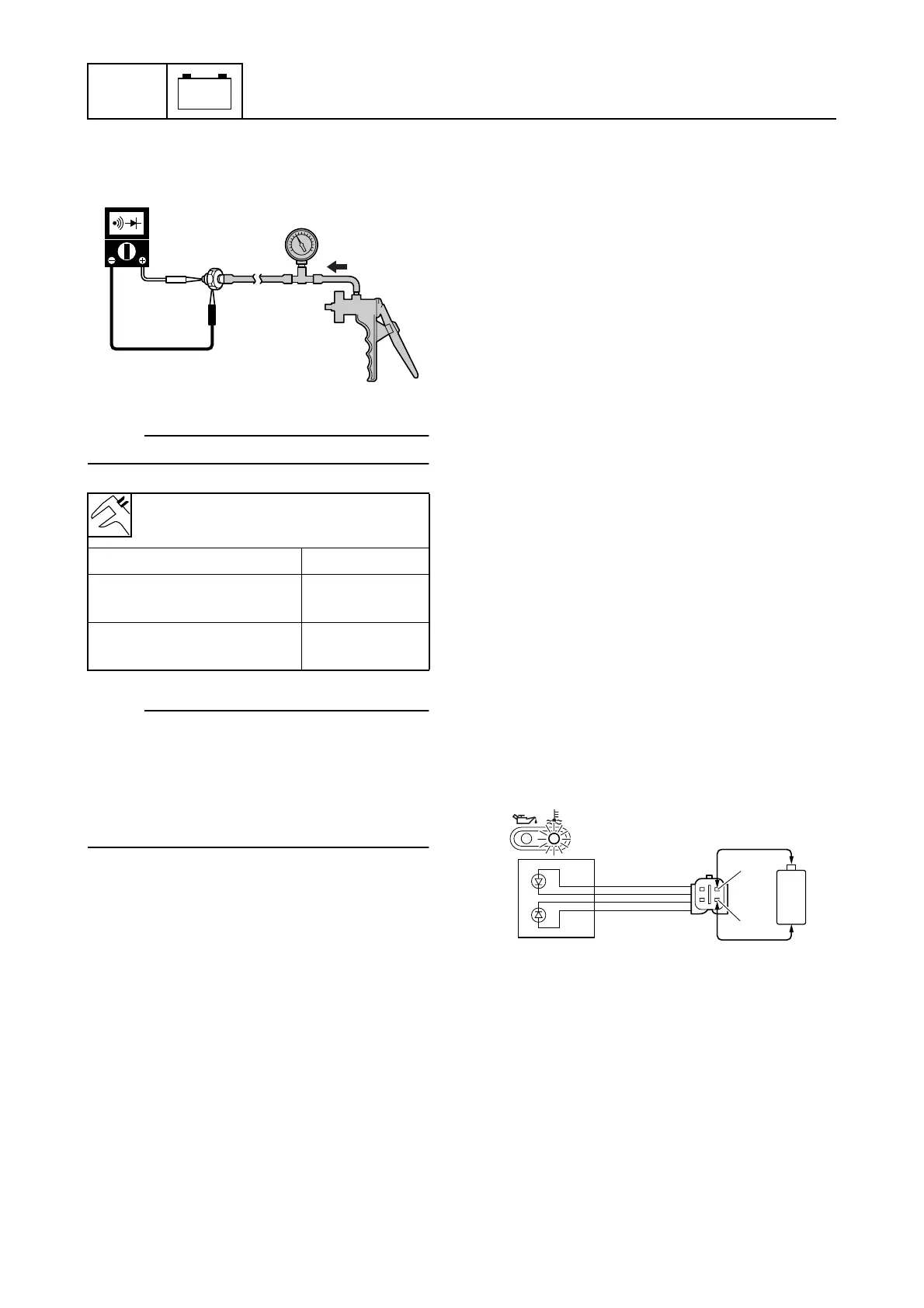
7. Check the oil pressure switch for continu-
ity at the specified pressures. Replace if
out of specification.
NOTE:
Slowly operate the special service tool.
NOTE:
Apply pressure to the oil pressure switch
gradually. The oil pressure switch is operat-
ing correctly if the digital tester indication
changes from continuity to no continuity in
the range of 15.5 ± 5.2 kPa (0.155 ± 0.052
kgf/cm
2
, 2.248 ± 0.754 psi).
8. Install the oil pressure switch, and then
connect the oil pressure switch connec-
tor.
Checking the warning indicator
assembly
1. Disconnect the thermo sensor coupler,
and then ground the brown/black (Br/B)
terminal (wiring harness end).
2. Start the engine, and then check that the
overheat warning indicator comes on
after about 60 seconds.
3. Push the engine stop button. (M model)
Turn the engine start switch to “OFF.” (E
and W model)
4. Disconnect the oil pressure switch con-
nector, and then ground the pink (P) lead
(wiring harness end).
5. Start the engine, and then check that the
oil pressure warning indicator comes on
after about 10 seconds.
6. Push the engine stop button. (M model)
Turn the engine start switch to “OFF.” (E
and W model)
7. Connect the thermo sensor coupler and
oil pressure switch connector.
8. Disconnect the warning indicator assem-
bly coupler.
9. Connect the yellow/black (Y/B) lead (M
model) or yellow (Y) lead (E and W
model) to the positive penlight battery
terminal (1.5 V) and connect the
pink/black (P/B) lead to the negative ter-
minal, and then check that the overheat
warning indicator comes on. Replace the
warning indicator assembly if it does not
come on.
Oil pressure switch continuity:
Oil pressure switch – Ground
Pressure Continuity
More than 15.5 kPa
(0.155 kgf/cm
2
, 2.248 psi)
No
Less than 15.5 kPa
(0.155 kgf/cm
2
, 2.248 psi)
Yes
S6AG8130
S67C8076
+
-
P/B
Y/B
È