ELEC
Electrical system
– +
8-3 67C3K11
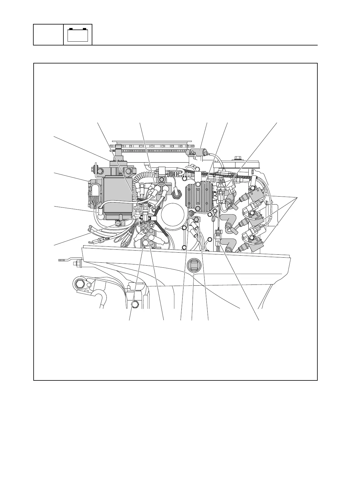
Port view
1 CDI unit
2 Starter motor (E and W model)
3 Starter relay (E and W model)
4 Pulser coil
5 Rectifier Regulator (E and W model)
6 Ignition coils
7 PTT terminal (PTT model)
8 PTT switch (R model with PTT)
9 Thermo sensor
0 PTT relay (PTT model)
È Fasten the negative battery cable and fuse
holder with the holder.
É Fasten the pulser coil lead, Rectifier Regulator
lead, and thermo sensor connector with the
plastic tie, making sure to align the tie with the
holder.
Ê Connect the PTT switch coupler. (R model
with PTT)
Ë Install the ground lead terminals using the
same nut.
S67C8006
345
2
1
0897
6
ÊË
Ì
Í
ÈÉ