SPEC
Specification
2-29 67C3K11
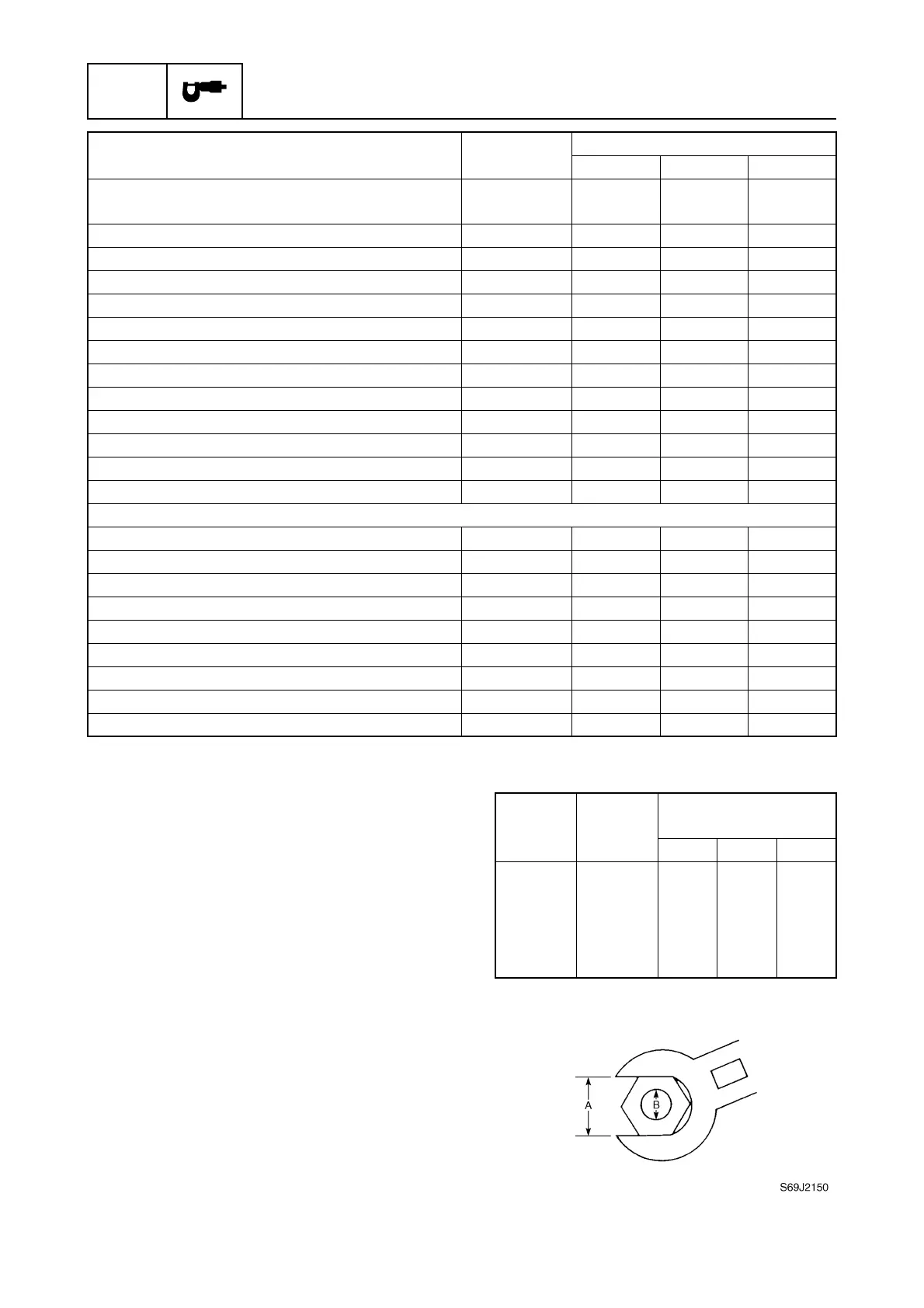
General torque
This chart specifies tightening torques for
standard fasteners with a standard ISO
thread pitch. Tightening torque specifications
for special components or assemblies are
provided in applicable sections of this man-
ual. To avoid warpage, tighten multi-fastener
assemblies in a crisscross fashion and pro-
gressive stages until the specified torque is
reached. Unless otherwise specified, torque
specifications require clean, dry threads.
Components should be at room temperature.
Bottom cowling PTT motor lead holder bolt (H
model with PTT)
M6 10 1.0 7.4
Upper mounting nut — 24 2.4 17.7
Steering arm stud bolt — 20 2.0 14.8
Upper case plug (L-transom model) M14 17 1.7 12.5
Baffle plate screw M5 3 0.3 2.2
Steering arm lock bolt M6 4 0.4 3.0
Engine oil drain bolt — 17 1.7 12.5
Exhaust manifold bolt M6 10 1.0 7.4
Upper case bolt M8 21 2.1 15.5
Self-locking nut — 22 2.2 16.2
Trim sensor cam screw M6 2 0.2 1.5
Anode bolt M6 8 0.8 5.9
Grease nipple — 30.32.2
PTT unit (PTT model)
PTT motor assembly bolt M6 7 0.7 5.2
Reservoir cap — 70.75.2
Gear pump bolt M4 4 0.4 3.0
Gear pump housing bolt M6 9 0.9 6.6
Valve lock screw — 60.64.4
Main valve — 70.75.2
Manual valve — 30.32.2
Tilt piston bolt M10 61 6.1 45.0
PTT cylinder end screw — 90 9.0 66.4
Part to be tightened Thread size
Tightening torques
N·mkgf·mft·lb
Nut (A) Bolt (B)
General torque
specifications
N·mkgf·mft·lb
8 mm M5 5 0.5 3.7
10 mm M6 8 0.8 5.9
12 mm M8 18 1.8 13.3
14 mm M10 36 3.6 26.6
17 mm M12 43 4.3 31.7