POWR
Power unit
5-49 67C3K11
6. Install the crankcase onto the cylinder
block, and then tighten the crankcase
bolts to the specified torques in 2 stages
and in the sequence shown.
NOTE:
• Apply engine oil to the threads of the crank-
case bolts.
• Do not turn the crankshaft until the crank-
shaft journal oil clearance measurement
has been completed.
7. Gently remove the crankcase, and then
measure the width of the compressed
Plastigauge (PG-1) on each crankshaft
journal. Replace the main bearings if out
of specification.
NOTE:
When loosening the crankcase bolts, loosen
them in the opposite order used for tighten-
ing.
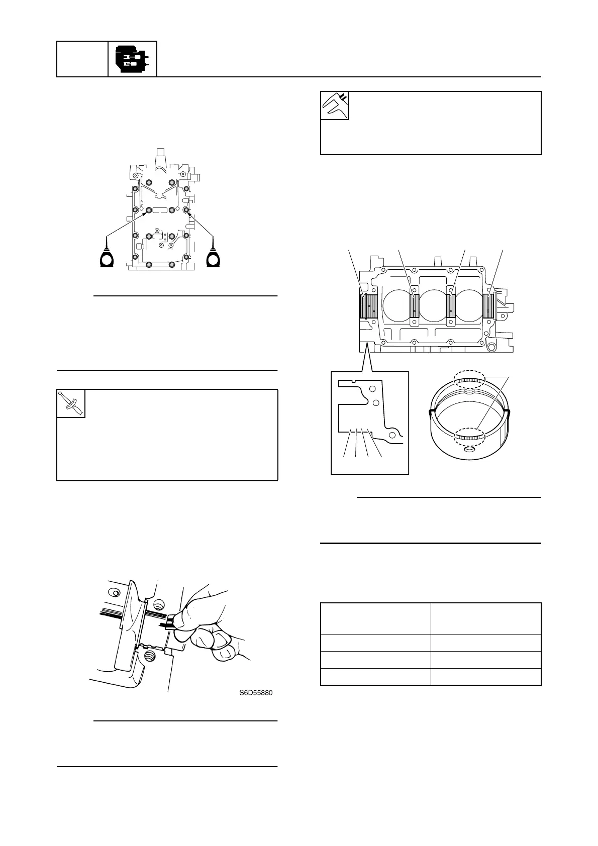
Selecting the crankshaft main
bearing
1. Check the stamped marks a, b, c, and
d on the cylinder block.
NOTE:
The stamped marks a, b, c, and d indi-
cate crankshaft main bearings #1, #2, #3,
and #4 respectively.
2. Select the suitable bearing color e for
the main bearings from the table.
Assembling the cylinder block
1. Assemble the piston 1, connecting rod
2, piston pin 3, and piston pin clips 4.
T
R
.
.
Crankcase bolt 1–8 (M8):
1st: 15 N·m (1.5 kgf·m, 11.1 ft·lb)
2nd: 30 N·m (3.0 kgf·m, 22.1 ft·lb)
Crankcase bolt 9–F (M6):
1st: 6 N·m (0.6 kgf·m, 4.4 ft·lb)
2nd: 12 N·m (1.2 kgf·m, 8.9 ft·lb)
S67C5145
12
34
56
78
90
AB
CD
EF
EE
Crankshaft journal oil clearance
(reference data):
0.012–0.044 mm
(0.0005–0.0017 in)
Stamped marks
a, b, c, and d
Bearing color e
ABlue
BBlack
CBrown
S67C5147
CCBC
CCBC
dcba
#4 #3 #2 #1
e