67C3K11 8-18
1
2
3
4
5
6
7
8
9
NOTE:
• To prevent the engine from starting when
cranking it, be sure to disconnect all spark
plug caps.
• Do not remove the clip from the engine
shut-off switch.
• If measuring the output peak voltage under
the unloaded conditions, disconnect the
charge coil connectors.
• When using the manual starter to crank the
engine to measure the output peak voltage
under the loaded conditions, turn the
engine start switch to “ON” (W model).
• When using the manual starter to crank the
engine, the voltage values may vary
depending on the speed at which the
starter handle is pulled.
2. Disconnect the charge coil connectors.
3. Measure the charge coil resistance.
Replace if out of specification.
4. Connect the charge coil connectors.
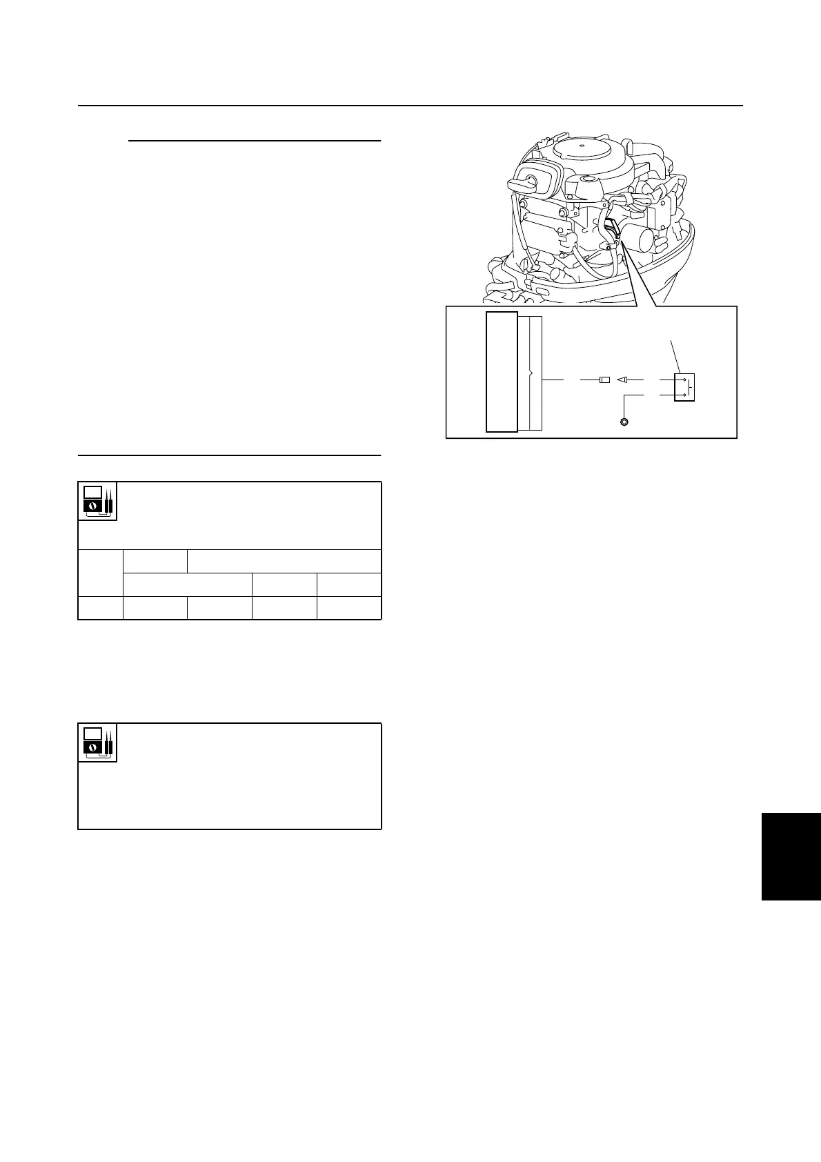
Checking the engine shut-off switch
(M model)
1. Disconnect the engine shut-off switch 1
connector and ground terminal.
Charge coil output peak voltage:
White/green (W/G) –
Green/white (G/W)
r/min
Unloaded
Loaded
Cranking 1,500 3,500
DC V 200 190 200 200
Charge coil resistance (reference
data):
White/green (W/G) –
Green/white (G/W)
660–710 Ω at 20 °C (68 °F)
S67C8045
WW
B
17
1
Ignition and ignition control system