67C3K11 3-10
1
2
3
4
5
6
7
8
9
5. Adjust the position of the shift cable joint
3 until its hole is aligned with the set pin
on the shift arm 4.
WARNING
The shift cable joint must be screwed in a
minimum depth of 8.0 mm (0.31 in) a.
NOTE:
Center the shift arm 4 in its free play b and
the shift cable in its free play c, and then
connect the shift cable.
6. Connect the shift cable joint 3, install the
clip 2, and then tighten the locknut 1.
7. Adjust the shift rod adjusting nut 5.
NOTE:
To adjust the shift rod adjusting nut 5, see
“Installing the lower unit” (6-19).
8. Check the gear shift for smooth opera-
tion.
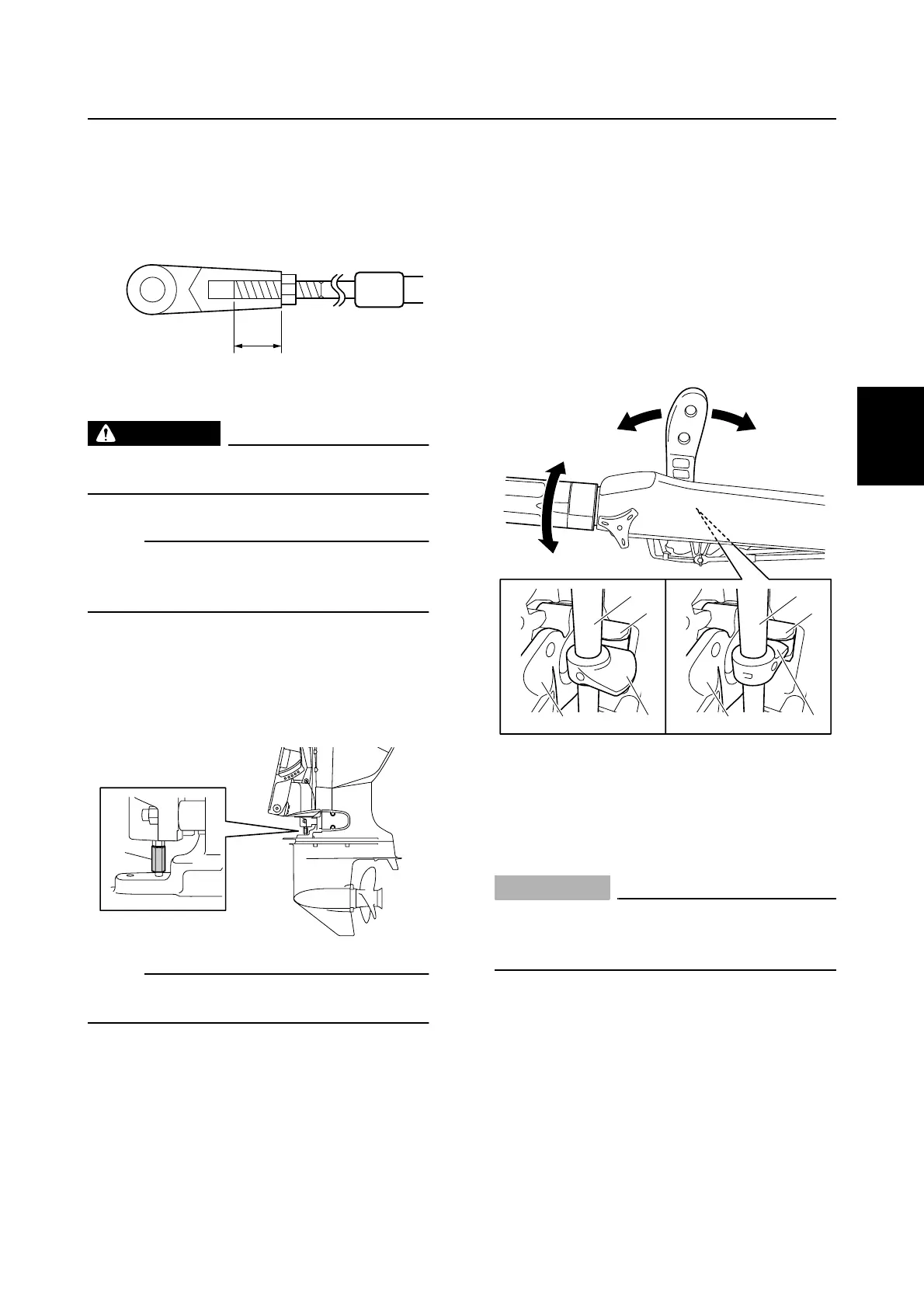
9. Turn the throttle grip to the fully closed
position, and then check that the shift-
lock cam d on the throttle shaft 6 is not
in the slot e in the shift lever cam 7 and
that the shift lever can be operated. Next,
turn the throttle grip to the fully open
position, and then check that the shift-
lock cam d on the throttle shaft 6 is fit-
ted into the slot e in the shift lever cam
7 and that the shift lever cannot be oper-
ated. (H model)
È Fully closed position
É Fully open position
Checking the start-in-gear protection
(M and W model)
CAUTION:
Be sure to remove the clip from the
engine shut-off switch before checking
the start-in-gear protection.
1. Set the shift lever to the F position or R
position, and then check that the starter
handle cannot be pulled. If the starter
rope can be pulled out normally, adjust
the start-in-gear protection cable.
S6AG3130
a
S67C3031
5
S67C3028
ÈÉ
6
e
d
7
6
e
d
7
Control system