67C3K11 8-26
1
2
3
4
5
6
7
8
9
3. Measure the lighting coil resistance.
Replace if out of specification.
4. Connect the lighting coil connectors.
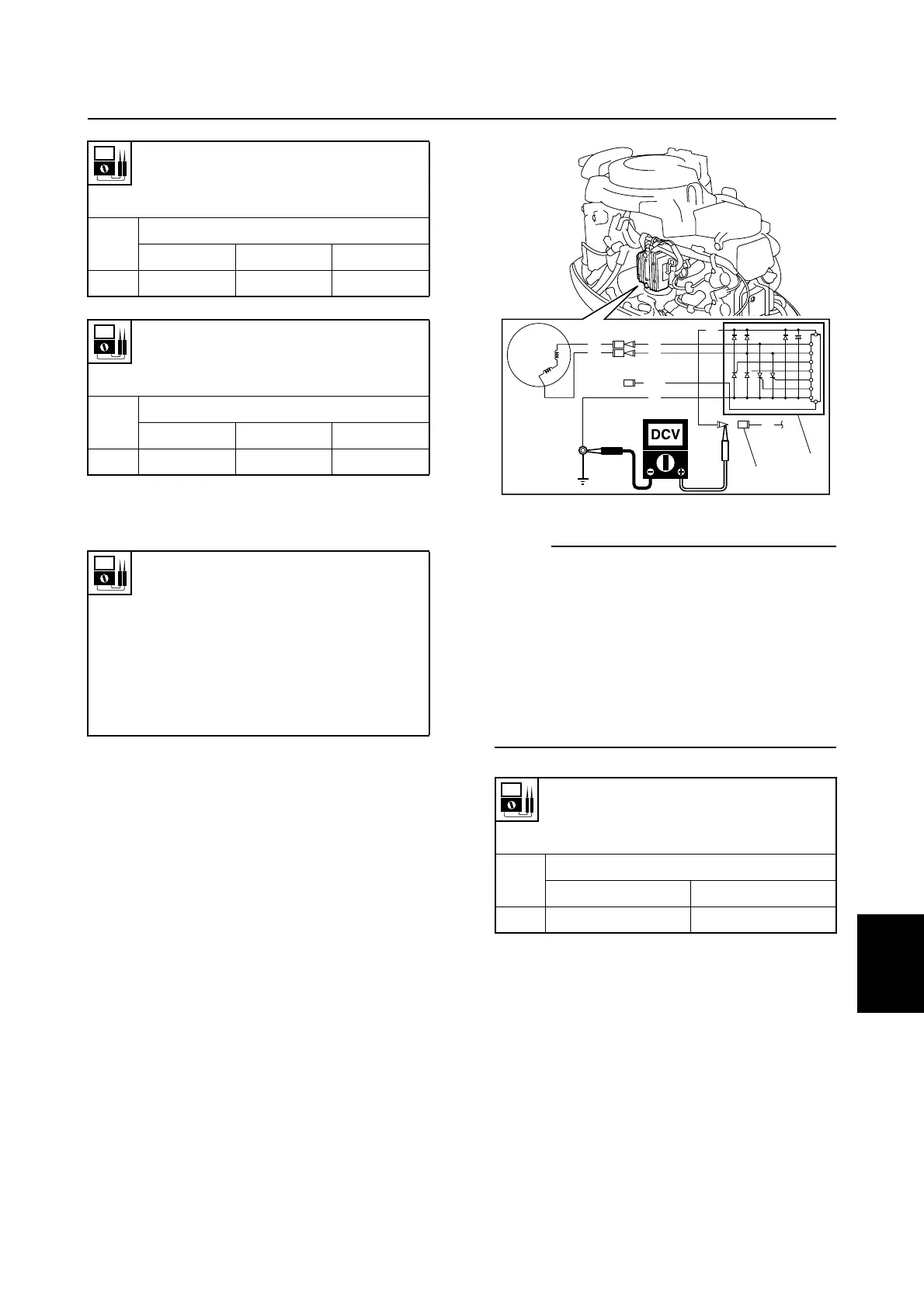
Checking the Rectifier Regulator (E
and W model)
1. Measure the Rectifier Regulator 1 out-
put peak voltage. Check the Rectifier
Regulator for continuity if the output peak
voltage is below specification.
NOTE:
• Measure the Rectifier Regulator output
peak voltage with the connector (R) 2 dis-
connected.
• Do not use peak voltage adapter B when
measuring the Rectifier Regulator output
peak voltage.
• Be sure to check the lighting coil before
measuring the Rectifier Regulator output
peak voltage.
2. Disconnect the Rectifier Regulator con-
nectors and terminal.
Lighting coil output peak voltage (6 A
model):
Yellow (Y) – Yellow (Y)
r/min
Unloaded
Cranking 1,500 3,500
DC V 14.1 39.7 95.2
Lighting coil output peak voltage (15
A model):
Yellow (Y) – Yellow (Y)
r/min
Unloaded
Cranking 1,500 3,500
DC V 8.4 28.5 66.6
Lighting coil resistance (6 A model)
(reference data):
Yellow (Y) – Yellow (Y)
0.9–1.1 Ω at 20 °C (68 °F)
Lighting coil resistance (15 A model)
(reference data):
Yellow (Y) – Yellow (Y)
0.26–0.28 Ω at 20 °C (68 °F)
Rectifier Regulator output peak
voltage:
Red (R) – Ground
r/min
Unloaded
1,500 3,500
DC V 13 13
S67C8059
Y
Y
Y
B
Y
R
Gy
R
1
2
Engine electric control system / Charging system