67C3K11 7-6
1
2
3
4
5
6
7
8
9
Removing the tiller handle
1. Disconnect the engine shut-off switch
leads (M model), or 10-pin main harness
and warning indicator assembly coupler
(E and W model).
NOTE:
To disconnect the leads or wiring harness,
see “Electrical component and wiring har-
ness routing” (8-1).
2. Disconnect the throttle cable 1 and shift
cable 2.
3. Remove the tiller handle and disassem-
ble it.
NOTE:
See the exploded diagram for disassembly
(7-1).
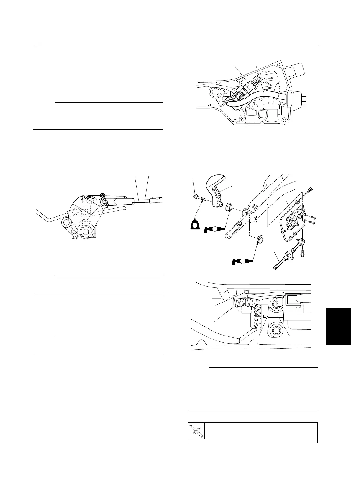
Installing the tiller handle
1. Assemble the tiller handle.
NOTE:
See the exploded diagram for assembly (7-
1).
2. Connect the 10-pin main harness 1 to
the engine start switch coupler 2 as
shown. (E and W model)
3. Install the shift link assembly 3, throttle
rod 4, and shift lever 5, and then
tighten the bolt 6 to the specified torque.
NOTE:
When installing the throttle rod 4, be sure to
align the mark a on the throttle rod gear with
the mark b on the rod guide and align the
mark c on the throttle lever gear with the
mark d on the shift bracket.
S67C7003
1 2
T
R
.
.
Shift lever bolt 6:
18 N·m (1.8 kgf·m, 13.3 ft·lb)
S67C7126
12
S67C7005
6
5
LT
242
A
A
4
3
S67C7112
a b
d
c
Tiller handle (H model)