67C3K11 8-14
1
2
3
4
5
6
7
8
9
È H model
É R model
Ê 7-pin main harness model
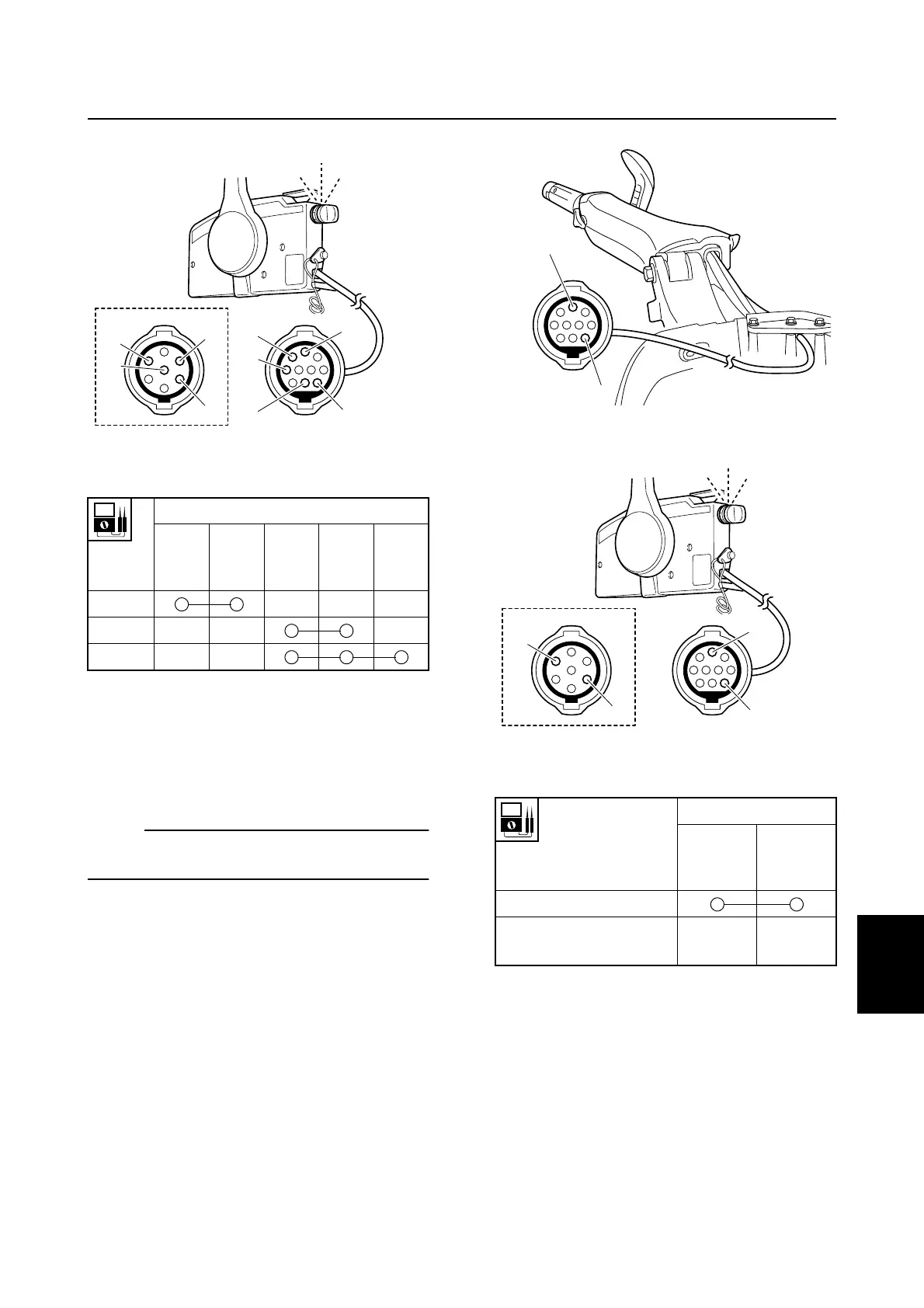
5. Connect the 10-pin (7-pin) main harness
coupler.
Checking the neutral switch (E and
W model)
NOTE:
Be sure to check the engine start switch for
continuity before checking the neutral switch.
1. Set the shift lever or remote control lever
to the N position.
2. Turn the engine start switch to “START,”
and then check the neutral switch for
continuity at the 10-pin (7-pin) main har-
ness coupler (tiller handle end or remote
control box end).
3. Set the shift lever or remote control lever
to the F position or R position, and then
check the neutral switch for continuity.
Check the wiring harness or replace the
neutral switch if out of specification.
È H model
É R model
Ê 7-pin main harness model
4. Turn the engine start switch to “OFF.”
5. Connect the 10-pin (7-pin) main harness
coupler.
Lead color
White
(W)
1
Black
(B)
2
Red
(R)
3
Yellow
(Y)
4
Brown
(Br)
5
Switch
position
OFF
ON
START
S67C8033
1
2
3
4
5
2
1
5
Ê
3
OFF
ON
START
É
Lead color
Red (R)
1
Brown
(Br) 2
Shift lever or remote
control lever position
N position
F position or R
position
S67C8070
2
1
È
S67C8036
1
2
2
Ê
1
OFF
ON
START
É
Starter motor (E and W model) / Starting system